In this paper, a configuration of a single-phase bidirectional
AC-DC converter and bidirectional DC-DC converter is proposed to transfer
electrical power from the grid to an electrical vehicle (EV) and from an EV to
the grid while keeping improved power factor of the grid. In first stage, a 230
V 50 Hz AC supply is converted in to 380V dc using a single-phase bidirectional
AC-DC converter and in the second stage, a bidirectional buck–boost dc-dc
converter is used to charge and discharge the battery of the PHEV (Plug-in
Hybrid Electric Vehicle). In discharging mode, it delivers energy back to the
grid at 230V, 50 Hz. A battery with the charging power of 1.2 kW at 120V is
used in PHEV. The buck-boost DC-DC converter is used in buck mode to charge and
in a boost mode to discharge the battery. A proportional-integral (PI)
controller is used to control the charging current and voltage. Simulated
results validate the effectiveness of proposed algorithm and the feasibility of
system.
KEYWORDS:
1.
Plug-in Hybrid
Electric Vehicle (PHEV)
2.
Bidirectional
AC-DC Converter
3.
DC-DC
Converter
4.
Vehicle to
grid (V2G)
5.
Electric drive
vehicle (EDVs)
SOFTWARE: MATLAB/SIMULINK
CIRCUIT DIAGRAM:

Fig.1
Proposed configuration for V2G and G2V Energy transfer
EXPECTED SIMULATION RESULTS:

Fig.2
Charging and discharging of PHEV battery (Full profile)

Fig.3
Charging and discharging of PHEV battery (in large view)

Fig.4.
Discharging and Charging of PHEV battery demonstrating unity
Power
factor operation

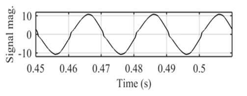
Fig.5
Waveform and harmonics spectrum of the discharging grid current

Fig.6
Waveform and harmonics spectrum of the Charging grid current
CONCLUSION:
The
proposed converter has delivered the AC current to/and from the grid at unity
power factor and at very low current harmonics which ultimately prolongs the
life of the converter and the battery and minimizes the possibility of
distorting the grid voltage. It also enables V2G interactions which could be utilized
to improve the efficiency of the grid.
REFERENCES:
[1]
Young-Joo Lee, Alireza Khaligh, and Ali Emadi, “Advanced Integrated Bidirectional
AC/DC and DC/DC Converter for Plug-In Hybrid Electric Vehicles,” IEEE Trans.
on Vehicular Tech. vol. 58, no. 8, pp. 3970-3980, Oct, 2009.
[2]
Bhim Singh, Brij N. Singh, Ambrish Chandra, Kamal Al-Haddad, Ashish Pandey and
Dwarka P. Kothari, “A review of single-phase improved power quality ac–dc
converters,” IEEE Trans. Industrial Electronics, vol. 50, no. 5, pp.
962-981, Oct. 2003.
[3]
M.C. Kisacikoglu, B. Ozpineci and L.M. Tolbert, "Examination of a PHEV
bidirectional charger system for V2G reactive power compensation," in Proc.
of Twenty-Fifth Annual IEEE Applied Power Electronics Conference and Exposition
(APEC), 2010, 21-25 Feb.2010, pp.458-465.
[4]
M.C. Kisacikoglu, B. Ozpineci and L.M. Tolbert, “Effects of V2G reactive power
compensation on the component selection in an EV or PHEV bidirectional
charger," in Proc. of Energy Conversion Congress and Exposition (ECCE),
2010 IEEE, 12-16 Sept. 2010, pp.870-876.
[5]
W. Kempton and J. Tomic, “Vehicle-to-grid power fundamentals: Calculating
capacity and net revenue,” J. Power Sources, vol. 144, no. 1, pp. 268–279,
Jun. 2005.