ABSTRACT:
This paper deals with a unity power factor (UPF) Cuk
converter EV (Electric Vehicle) battery charger having a high frequency
transformer isolation instead of only a single phase front end converter used
in vehicle's conventional battery chargers. The operation of the proposed
converter is defined in various modes of the converter components i.e. DCM (Discontinuous
Conduction Mode) or CCM (Continuous Conduction Mode) along with the optimum
design equations. In this way, this isolated PFC converter makes the input
current sinusoidal in shape and improves input power factor to unity. Simulation
results for the proposed converter are shown for charging a lead acid EV
battery in constant current constant voltage (CC-CV) mode. The rated full load
and varying input supply conditions have been considered to show the improved power
quality indices as compared to conventional battery chargers. These indices
follow the international IEC 61000-3-2 standard to give harmonic free input
parameters for the proposed circuit.
KEYWORDS:
1.
UPF Cuk Converter
2.
Battery Charger
3.
Front end converter
4.
CC-CV mode
5.
IEC 61000-3-2 standard
SOFTWARE: MATLAB/SIMULINK
BLOCK DIAGRAM:

Fig.
1 General Schematic of an EV Battery Charger with PFC CUK Converter

(a)

(b)

(c)
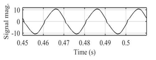
Fig.2
Simulated performance of the isolated Cuk converter in rated condition (a)
rated input side and output side quantities (b-c) harmonic analysis of the current
at source end

(a)

(b)

(c)
Fig.3
Simulated performance of the isolated Cuk converter while input is varied to
270V (a) rated input side and output side quantities (b-c) harmonic analysis of
the current at source end

(a)
(b)

(c)
Fig.4
Simulated performance of the isolated Cuk converter while input is reduced to
270V (a) rated input side and output side quantities (b-c) harmonic analysis of
the current at source end

(a)

(b)

(c)
Fig.5
Simulated performance of the isolated Cuk converter at light load condition (a)
rated input side and output side quantities (b-c) harmonic analysis of the
current at source end
CONCLUSION:
An
isolated Cuk converter based battery charger for EV with remarkably improved PQ
indices along with well regulated battery charging voltage and current has been
designed and simulated. The converter performance has been found satisfactory
and well within standard for rated as well as different varying input rms value
of supply voltages. The considerably improved THD in the current at the source
end makes the proposed system an attractive solution for efficient charging of
EVs at low cost. The proposed UPF converter performance has been tested to show
its suitability for improved power quality based charging of an EV battery in
CC-CV mode. Moreover, the cascaded dual loop PI controllers are tuned to have
the smooth charging characteristics along with maintaining the low THD in mains
current. The proposed UPF converter topology have the inherent advantage of low
ripples in input and output side due to the added input and output side
inductors. Therefore, the life cycle of the battery is increased. MATLAB based simulation
shows the performance assessment of the proposed charger for the steady state
and dynamics condition which clearly state that the proposed charger can
sustain the sudden disturbances in supply for charging the rated EV battery
load. Moreover, during whole disturbances in supply voltage, the power quality
parameters at the input side, are maintained within the IEC 61000-3-2 standard
and THD is also very low.
REFERENCES:
[1]
Limits for Harmonics Current Emissions (Equipment current ≤ 16A per Phase),
International standards IEC 61000-3-2, 2000.
[2]
Muhammad H. Rashid, “Power Electronics Handbook, Devices, Circuits, and
Applications”, Butterworth-Heinemann, third edition, 2011.
[3]
N. Mohan, T. M. Undeland, and W. P. Robbins, Power Electronics: Converters,
Applications and Design. Hoboken, NJ, USA: Wiley, 2009.
[4]
B. Singh, S. Singh, A. Chandra and K. Al-Haddad, “Comprehensive Study of
Single-Phase AC-DC Power Factor Corrected Converters With High-Frequency
Isolation”, IEEE Trans. Industrial Informatics, vol. 7, no. 4, pp.
540-556, Nov. 2011.
[5]
A. Abramovitz K. M. Smedley "Analysis and design of a tapped-inductor buck–boost
PFC rectifier with low bus voltage" IEEE Trans. Power Electron.,
vol. 26 no. 9 pp. 2637-2649 Sep. 2011.


