ABSTRACT
Direct torque control (DTC) is known to be a
promising candidate for interior permanent magnet synchronous motor (IPMSM)
drives. It provides fast dynamic response and good immunity to parameter
variations. However, except for its merits, DTC also suffers from two major
problems of variable switching frequency and large torque ripples. Research
proposals have been published to solve these problems. Nonetheless, most of the
proposals present very complex control algorithms. This paper proposes a
constant switching frequency based DTC algorithm for IPMSM drives. It is
consisted of only one PI regulator and one triangular-wave carrier. The
proposed algorithm reduces the torque ripples to a noticeable extent. In-depth
analysis and design guidelines of the proposed controller are given. Simulation
and experiment results are provided to verify the effectiveness of the proposed
method.
KEYWORDS
1.
Interior
permanent magnet synchronous motor
2.
Direct torque
control
3.
Constant
switching frequency
4.
Torques ripple
5.
Carrier Controller
stability.
SOFTWARE: MATLAB/SIMULINK
BLOCK DIAGRAM:

Fig.
1 Block diagram of the proposed constant switching frequency control algorithm.
EXPECTED SIMULATION RESULTS


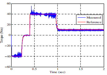
Fig.
2 Response of torque reversal from -4Nm to 4Nm. (a) Classical DTC : reference
torque (red), real torque (blue); (b) Proposed constant switching
frequency DTC : reference torque (red), real torque (blue).


Fig.
3 Response of speed reversal from -375r/min to 375r/min. (a) Classical DTC :
subplot 1: rotor electrical speed, subplot 2: reference torque (red),
real torque (blue); (b) Proposed constant switching frequency DTC :
subplot 1: rotor electrical speed, subplot 2: reference torque (red),
real torque (blue).


Fig.
4 FFT analysis of line current at 375 r/min (a) Classical DTC : subplot 1: line
current, subplot 2: Frequency Spectrum of line current; (b) Proposed constant
switching frequency DTC : subplot 1 : line current, subplot 2: Frequency
Spectrum of line current.
CONCLUSION
This
paper presents a simple but effective constant switching frequency based direct
torque control method. It significantly reduces the torque ripples and
maintains nearly all the merits of the classical DTC. The proposed torque
regulator is consisted of one PI controller and one fixed frequency
triangular-wave carrier. This benefits the real-time implementation by reducing
the computational burden. In-depth modeling and small-signal analysis of the
proposed regulator are provided. The design of stable torque regulator by using
conventional bode plots is discussed. Both simulation and experimental results
are given to verify the performance of the proposed control method.
REFERENCES
[1]
Takahashi and T. Noguchi, “A new quick response
and high efficiency control strategy of an induction motor,” IEEE Trans.
Ind. Applicat., vol. IA-22, no. 5, pp. 820 - 827, 1986.
[2]
L. Zhong and M.F. Rahman, W.Y. Hu, K.W. Lim,
M.A. Rahman, “A direct torque controller for permanent magnet synchronous motor
drives,” IEEE Transactions on Energy Conversion, vol. 14, no. 3, pp. 637
- 642, 1999.
[3]
L. Zhong and M.F. Rahman, W. Y. Hu and K.W. Lim,
“Analysis of Direct Torque Control in Permanent Magnet Synchronous Motor Drives,”
IEEE Trans. Power Electron., vol. 12, no. 3, pp. 528-536, May 1997.
[4]
J.-K. Kang and S.-K. Sul, “Analysis of inverter
switching frequency in DTC of induction machine based on hysteresis bands,” IEEE
Trans. Ind. Electron., vol. 48, no. 3, pp. 545 - 553, Oct. 2001.
[5]
K. Gulez, A.A. Adam and H. Pastaci, “A Novel
Direct Torque Control Algorithm for IPMSM With Minimum Harmonics and Torque
Ripples,” IEEE Trans. Mechatron., vol. 12, no. 2, pp. 223 - 227, 2007.