Damping Power System
Oscillations Using a Hybrid Series Capacitive Compensation Scheme
ABSTRACT:
The recently proposed phase imbalanced series capacitive
compensation concept has been shown to be effective in enhancing power system
dynamics as it has the potential of damping power swing as well as sub synchronous
resonance oscillations. In this paper, the effectiveness of a “hybrid” series
capacitive compensation scheme in damping power system oscillations is
evaluated. A hybrid scheme is a series capacitive compensation scheme,
where two phases are compensated by fixed series capacitor (C) and the third
phase is compensated by a TCSC in series with a fixed capacitor (Cc). The
effectiveness of the scheme in damping power system oscillations for various
network conditions, namely different system faults and tie-line power flows is
evaluated using the EMTP-RV time simulation program.
KEYWORDS
1. FACTS Controllers
2. phase
imbalance
3. series compensation
4. thyristor
controlled series capacitor
SOFTWARE: MATLAB/SIMULINK
BLOCK DIAGRAM:

Fig.
1. A schematic diagram of the hybrid series compensation scheme.

Fig.
2. Test benchmark.
EXPECTED SIMULATION RESULTS:


Fig.
3. Generator load angles, measured with respect to generator 1 load angle,
during and after clearing a three-phase fault at bus 4 (Load Profile A).


Fig.
4. Generator load angles, measured with respect to generator 1 load angle,
during and after clearing a three-phase fault at bus 4 (Load Profile B).

Fig.
5. Structure of a dual-channel power oscillations damping controller.


Fig.
6. Generator load angles, measured with respect to generator 1 load angle,
during and after clearing a three-phase fault at bus 4 (Load Profile B, dual-channel
controller).


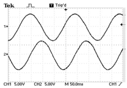
Fig.
7. Phase voltages, VX-Y across the hybrid single-phase-TCSC scheme on L1 during
and after clearing a three-phase fault at bus 4 (Load Profile B, dual channel supplemental
controllers, Pair 2).
CONCLUSION:
The
paper presents the application of a new hybrid series capacitive compensation
scheme in damping power system oscillations. The effectiveness of the presented
scheme in damping these oscillations is demonstrated through several digital
computer simulations of case studies on a test
benchmark.
The presented hybrid series capacitive compensation scheme is feasible,
technically sound, and has an industrial application potential.
REFERENCES:
[1]
Narain G. Hingorani and Laszlo Gyugyi, “Understanding FACTS, Concepts and
Technology of Flexible AC Transmission Systems,” IEEE Press, 2000.
[2]
M. Klein, G.J. Rogers and P. Kundur, “A Fundamental Study of Inter- Area
Oscillations in Power Systems,” IEEE Transactions on Power Systems, Vol. 6, No.
3, 1991, pp. 914-921. Fig. 9. Phase voltages, VX-Y across the hybrid
single-phase-TCSC scheme on L1 during and after clearing a three-phase fault at
bus 4 (Load Profile B, dual channel supplemental controllers, Pair 2).
[3]
E.V. Larsen, J.J. Sanchez-Gasca and J.H. Chow, “Concepts for Design of FACTS
Controllers to Damp Power Swings,” IEEE Transactions on Power Systems, Vol. 10,
No. 2, May 1995, pp. 948-956.
[4]
B. Chaudhuri, B. Pal, A. C. Zolotas, I. M. Jaimoukha, and T. C. Green, “Mixed-sensitivity
Approach to H Control of Power System Oscillations Employing Multiple FACTS
Devices,” IEEE Transactions on Power System, Vol. 18, No. 3, August 2003, pp.
1149–1156.
[5]
B. Chaudhuri and B. Pal, “Robust Damping of Multiple Swing Modes Employing
Global Stabilizing Signals with a TCSC,” IEEE Transactions on Power System,
Vol. 19, No. 1, February 2004, pp. 499–506.