asokatechnologies@gmail.com 09347143789/09949240245

Search This Blog

Thursday 27 October 2022

Vehicle-To-Grid Technology in a Micro-grid Using DC Fast Charging Architecture

ABSTRACT:

 Electric Vehicle (EV) batteries can be utilized as potential energy storage devices in micro-grids. They can help in micro-grid energy management by storing energy when there is surplus (Grid-To-Vehicle, G2V) and supplying energy back to the grid (Vehicle-To-Grid, V2G) when there is demand for it. Proper infrastructure and control systems have to be developed in order to realize this concept. Architecture for implementing a V2G-G2V system in a micro-grid using level-3 fast chargingof EVs is presented in this paper. A micro-grid test system is modeled which has a dc fast charging station for interfacing the EVs. Simulation studies are carried out to demonstrate V2G-G2V power transfer. Test results show active power regulation in the micro-grid by EV batteries through G2V-V2G modes of operation. The charging station design ensures minimal harmonic distortion of grid injected current and the controller gives good dynamic performance in terms of dc bus voltage stability.

KEYWORDS:

1.      DC fast charging

2.      Electric vehicle

3.      Grid connected inverter

4.      Micro-grid

5.      Off-board charger

6.      Vehicle-to-grid

SOFTWARE: MATLAB/SIMULINK

 BLOCK DIAGRAM:


 Fig. 1. EV charging station for fast dc charging

 EXPECTED SIMULATION RESULTS:


Fig. 2. Voltage, current, and SOC of EV1 battery during V2G operation


Fig. 3. Voltage, current, and SOC of EV2 battery during G2V operation


Fig. 4. Active power profile of various components in the system


Fig. 5. Reference current tracking by inverter controller


Fig. 6. Grid voltage and grid injected current during V2G-G2V operation


Fig. 7. Harmonic spectrum and THD of grid-injected current

 CONCLUSION:

Modeling and design of a V2G system in a micro-grid using dc fast charging architecture is presented in this paper. A dc fast charging station with off-board chargers and a grid connected inverter is designed to interface EVs to the micro- grid. The control system designed for this power electronic interface allows bi-directional power transfer between EVs and the grid. The simulation results show a smooth power transfer between the EVs and the grid, and the quality of grid injected current from the EVs adheres to the relevant standards. The designed controller gives good dynamic performance in terms of dc bus voltage stability and in tracking the changed active power reference. Active power regulation aspects of the micro grid are considered in this work, and the proposed V2G system can be utilized for several other services like reactive, power control and frequency regulation. Design of a supervisory controller which gives command signals to the individual EV charger controllers is suggested for future research.

REFERENCES:

[1] C. Shumei, L. Xiaofei, T. Dewen, Z. Qianfan, and S. Liwei, “The construction and simulation of V2G system in micro-grid,” in Proceedings of the International Conference on Electrical Machines and Systems, ICEMS 2011, 2011, pp. 1–4.

[2] S. Han, S. Han, and K. Sezaki, “Development of an optimal vehicle-to- grid aggregator for frequency regulation,” IEEE Trans. Smart Grid, vol. 1, no. 1, pp. 65–72, 2010.

[3] M. C. Kisacikoglu, M. Kesler, and L. M. Tolbert, “Single-phase on-board bidirectional PEV charger for V2G reactive power operation,” IEEE Trans. Smart Grid, vol. 6, no. 2, pp. 767–775, 2015.

[4] A. Arancibia and K. Strunz, “Modeling of an electric vehicle charging station for fast DC charging,” in Proceedings of the IEEE International Electric Vehicle Conference (IEVC), 2012, pp. 1–6.

[5] K. M. Tan, V. K. Ramachandaramurthy, and J. Y. Yong, “Bidirectional battery charger for electric vehicle,” in 2014 IEEE Innovative Smart Grid Technologies - Asia, ISGT ASIA 2014, 2014, pp. 406–411.

Single-phase Grid-connected PV System with Golden Section Search-based MPPT Algorithm*

 ABSTRACT:

 Maximum power point tracking (MPPT) is a technique employed for with variable-power sources, such as solar, wind, and ocean, to maximize energy extraction under all conditions. The commonly used perturb and observe (P&O) and incrementalconductance (INC) methods have advantages such as ease of implementation, but they also have the challenge of selecting the most optimized perturbation step or increment size while considering the trade-off between convergence time and oscillation. To address these issues, an MPPT solution for grid-connected photovoltaic (PV) systems is proposed that combines the golden section search (GSS), P&O, and INC methods to simultaneously achieve faster convergence and smaller oscillation, converging to the MPP by repeatedly narrowing the width of the interval at the rate of the golden ratio. The proposed MPPT technique was applied to a PV system consisting of a PV array, boost chopper, and inverter. Simulation and experimental results verify the feasibility and effectiveness of the proposed MPPT technique, by which the system is able to locate the MPP in 36 ms and regain a drifting MPP in approximately 30 ms under transient performance. The overall MPPT efficiency is 98.99%.

 KEYWORDS:

1.      Grid-connected system

2.      Maximum power point tracking (MPPT)

3.      Photovoltaic (PV) system

4.      Single-phase inverter

SOFTWARE: MATLAB/SIMULINK

BLOCK DIAGRAM:


Fig. 1 Control block diagram of the single-phase grid-connected PV system

 EXPECTED SIMULATION RESULTS:

Fig. 2 Simulation results under the conditions of S=237 W/m2, T=13.9


Fig. 3 Simulation results under the conditions of S=930 W/m2, T=37.5

CONCLUSION: 

In this paper, a GSS-based multi-stage MPPT technique that combines GSS with P&O and INC was proposed to achieve fast convergence to the MPP with small oscillation. The proposed multi-stage MPPT technique starts by searching the vicinity of the MPP by P&O in the first stage. Then, it quickly narrows the width of the interval with the golden ratio in the second stage, and the located MPP by is verified by the INC method in the third stage. The advantages of P&O, GSS, and INC are exploited, while their disadvantages are avoided. Therefore, this MPPT algorithm provides fast response and high tracking efficiency, as shown through the simulation and experimental results. The simulation and experimental results verified the feasibility and effectiveness of the proposed MPPT technique. The proposed MPPT technique mainly targets the MPP of a unimodal function, i.e., the curve has only one extremum, but it is not suited to multimodal functions, i.e., the curve has multiple extrema when partial shading happens. Thus, to apply the proposed MPPT technique to partial shading conditions, more points must be inserted into the GSS scheme to locate the MPP. The application of the proposed MPPT technique under the partial shading condition remains as future work.

REFERENCES:

[1] U.S. Energy Information Administration (EIA), Where Solar is found and used. [2020-09-05]. https:// www.eia.gov/energyexplained/solar/where-solar-is-found. php.

[2] L Zhang, F K Jiang, D W Xu, et al. Two-stage transformerless dual-buck PV grid-connected inverters with high efficiency. Chinese Journal of Electrical Engineering, 2018, 4(2): 36-42.

[3] S Xu, L Chang, R Shao. Evolution of single-phase power converter topologies underlining power decoupling. Chinese Journal of Electrical Engineering, 2016, 2(1): 24-39.

[4] R W Erickson, D Maksimovic. Fundamentals of power electronics. Boston: Springer, 2001.

[5] P K Bonthagorla, S Mikkili. Performance investigation of hybrid and conventional PV array configurations for grid-connected/standalone PV systems. CSEE J. Power Energy Syst., 2020: 1-16.

Si/SiC Hybrid 5-level Active NPC Inverter for Electric Aircraft Propulsion Drive Applications

ABSTRACT:

 Medium voltage DC(MVDC) system is considered as a promising technology to improve the efficiency and power density of electric aircraft propulsion(EAP) drives. To adapt to the MVDC voltage level and achieve high drive performance, a five-levelactive neutral point clamped(5L-ANPC) inverter consisting of three-level ANPC and flying capacitor circuits is investigated, which possesses higher voltage capability, lower output harmonics, as well as mitigated dv/dt and common-mode voltage. To fulfill the requirements of high-speed operation and pursue further enhanced efficiency and power density of the inverter for the next-generation EAP drives, Silicon Carbide(SiC) semiconductor devices are considered for implementing the 5L-ANPC inverter. However, the large commutation loops associated with certain switching states of the inverter lessen the benefits of configuring all the switches as SiC devices. As a result, a hybrid Si/SiC 5L-ANPC inverter is developed with a synchronous optimal pulse(SOP) width modulation strategy for controlling the switches in cell 2 and finite-control-set model predictive controller(FCS-MPC) for those in cell 3 of the inverter. Consequently, in the proposed topology, the SiC devices are merely used for the high-frequency switches in cell 3 and the rest of the low-frequency switches are configured with Si IGBTs. This Si/SiC hybrid ANPC inverter concurrently provides high efficiency and low implementation cost at high-speed operation mode. Simulation and experimental results are provided to verify the effectiveness of the proposed hybrid inverter.

 KEYWORDS:

1.      Five-level ANPC

2.      Flying capacitor

3.      SOP

4.      FCS-MPC

5.      Carrier-based modulation

6.      High efficiency

7.      MVDC

8.      Electric aircraft propulsion

SOFTWARE: MATLAB/SIMULINK

BLOCK DIAGRAM:


 Fig. 1 High frequency commutation loops of a conventional 5L-ANPC between: S7-S8 (dash-dotted line), and S5 S6 (positive and negative half-cycles in dashed lines)

 EXPECTED SIMULATION RESULTS:


 Fig. 2 Simulation results using hybrid FCS-MPC with λ1=2.5 and λ2=0; From top to bottom: load current, line-line voltage, line-neutral voltage, DC-link capacitors voltage, FCs voltage, and CMV


Fig. 3 Simulation results using hybrid FCS-MPC with λ1=4 and λ2=0.08; From top to bottom: load current, line-line voltage, line-neutral voltage, DC-link capacitors voltage, FCs voltage, and CMV


CONCLUSION:

A three-phase Si/SiC hybrid 5L-ANPC inverter for electric aircraft propulsion drive applications has been presented in this paper. To simultaneously attain higher efficiency and low implementation cost, only the cell 3 of the inverter has been configured with SiC devices, while the rest of the switches are designed with Si IGBTs switching at lower frequencies. Furthermore, to overcome the issue of large commutation loops with the switches in cell 2 and also pursue further loss reduction, synchronous optimal PWM has been applied as a low frequency modulation method. Both thermal and electrical simulation results have been provided to demonstrate the effectiveness of the proposed inverter and the related PWM strategy. Experimental Results have been presented to demonstrate the efficacy of the hybrid “SOP+MPC” modulation method. Test results have verified the performance of the proposed method and the fact that this hybrid inverter topology provides high efficiency and low output harmonic distortions at low cost.

REFERENCES:

[1] X Zhang, C L Bowman, T C O’Connell, et al. Large electric machines for aircraft electric propulsion. IET Electric Power Applications, 2018, 12(6): 767-779.

[2] A Adib, K K Afridi, M Amirabadi, et al. E-mobility: Advancements and challenges. IEEE Access, 2019, 7: 165226-165240.

[3] J He, D Zhang, D Torrey. Recent advances of power electronics applications in more electric aircrafts. AIAA/IEEE Electric Aircraft Technologies Symposium (EATS), July 12-14, 2018, Cincinnati, OH: IEEE 2018: 1-8.

[4] L G Franquelo, J Rodriguez, J I Leon, et al. The age of multilevel converters arrives. IEEE Industrial Electronics Magazine, 2008, 2(2): 28-39.

[5] R K Behera, S P Das. Multilevel converter fed induction motor drive for industrial and traction drive. IEEE Potentials, 2010, 29(5): 28-32.

Seven-Level Inverter with Reduced Switches for PV System Supporting Home-Grid and EV Charger

ABSTRACT:

This paper proposes a simple single-phase new pulse-width modulated seven-level inverter architecture for photovoltaic (PV) systems supporting home-grid with electricvehicle (EV) charging port. The proposed inverter includes a reduced number of power components and passive elements size, while showing less output-voltage total harmonic distortion (THD), and unity power factor operation. In addition, the proposed inverter requires simple control and switching strategies compared to recently published topologies. A comparative study was performed to compare the proposed inverter structure with the recent inverter topologies based on the number of components in the inverter circuit, number of components per output-voltage level, average number of active switches, THD, and operating efficiency as effective parameters for inverter performance evaluation. For design and validation purposes, numerical and analytical models for a grid-tied solar PV system driven by the proposed seven-level inverter were developed in MATLAB/Simulink environment. The inverter performance was evaluated considering grid-integration and stand-alone home with level-2 AC EV charger (3–6 kW). Compared with recently published topologies, the proposed inverter utilizes a reduced number of power components (7 switches) for seven-level terminal voltage synthesis. An experimental prototype for proposed inverter with the associated controller was built and tested for a stand-alone and grid-integrated system. Due to the lower number of ON-switches, the inverter operating efficiency was enhanced to 92.86% with load current THD of 3.43% that follows the IEEE standards for DER applications.

KEYWORDS:

1.      DC-AC converter

2.      Electric vehicles

3.      Home grid

4.      Maximum power point tracking (MPPT)

5.      Multilevel inverter

6.      Photovoltaic (PV) system

7.      Seven-level inverter

SOFTWARE: MATLAB/SIMULINK

BLOCK DIAGRAM:  


Figure 1. Circuit configuration of solar PV system in integrated with the grid and EV loads via the proposed 7level-inverter.

EXPECTED SIMULATION SYSTEM:


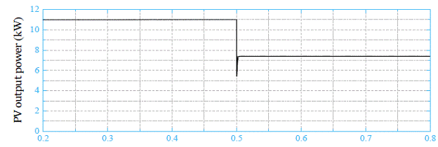
(a) Solar irradiation


(b) PV current


(c) PV voltage

Figure 2. Cont

time(s)

(d)PV power

Figure 3. the pv panel current, voltage, and power.


Figure 4. multi- Level inverter output voltage.


Figure 
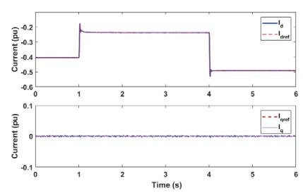
5. the injected current, voltage, and power variation. (a) Grid voltage and current; (b) Grid injected power.


Figure 6. The reference and actual injected currents of the seven-level inverter at irradiance variation.


Figure 7. Simulation results of the proposed 7-level inverter as level-2 EV charger (240 V, 3:6 kW); (a) loading profile, (b) multilevel output voltage, and (c) inverter voltage/pulsating current


Figure 8. Simulation results of the proposed 7-level inverter for house loads voltage control (2 kW). (a) Load reference and actual voltages, (b) Load voltage and current

CONCLUSION:

This paper has presented a new topology of a single-phase seven-level inverter as an interface for grid-integrated and stand-alone solar PV systems. The circuit configuration This paper has presented a new topology of a single-phase seven-level inverter as an interface for grid-integrated and stand-alone solar PV systems. The circuit configuration This paper has presented a new topology of a single-phase seven-level inverter as an interface for grid-integrated and stand-alone solar PV systems. The circuit configuration and operation principle of the proposed inverter have been presented in detail a long with    the switching patterns and control strategy. A comparative study between the proposed inverter structure and the recent MLI topologies is enriched to reveal the features of the proposed inverter. The proposed MLI structure considers a reduced number of power switches, NC/L, and NAVG/Pole, which enhances the inverter operating efficiency and decreases its cost. Only seven switches have been utilized to synthesis voltage waveform of seven levels at the output terminals. The performance of the proposed inverter and associated control was investigated for grid-integrated and stand-alone PV systems based on simulation and experimental tests. The test platform includes a boost converter with MPPT control, which feeds the front-end of the proposed MLI. The results show that the proposed inverter exhibits an improved steady state response, and minimum settling time (i.e., 5 ms). THD of both voltage and current waveforms during grid-integration and stand-alone operations is 3.43%, which follows the IEEE-1547 harmonic standards for DER applications. In addition, the inverter offers a high operating efficiency of 92.86%, compared to most of the recently published topologies surveyed in this paper.

REFERENCES:

1. Solangi, K.; Islam, M.; Saidur, R.; Rahim, N.; Fayaz, H. A review on global solar energy policy. Renew. Sustain. Energy Rev. 2011, 15, 2149–2163. [CrossRef]

2. Ali, A.I.; Sayed, M.A.; Mohamed, E.E. Modified efficient perturb and observe maximum power point tracking technique for grid-tied PV system. Int. J. Electr. Power Energy Syst. 2018, 99, 192–202. [CrossRef]

3. Sayed, M.A.; Mohamed, E.; Ali, A. Maximum Power Point Tracking Technique for Grid tie PV System. In Proceedings of the 7th International Middle-East Power System Conference, (MEPCON’15), Mansoura University, Dakahlia Governorate, Egypt, 15–17 December 2015.

4. Ali, A.I.; Mohamed, E.E.; Sayed, M.A.; Saeed, M.S. Novel single-phase nine-level PWM inverter for grid connected solar PV farms. In Proceedings of the 2018 International Conference on Innovative Trends in Computer Eng. (ITCE), Aswan, Egypt, 19–21 February 2018; IEEE: Piscataway, NJ, USA, 2018; pp. 345–440.

5. Youssef, A.-R.; Ali, A.I.; Saeed, M.S.; Mohamed, E.E. Advanced multi-sector P&O maximum power point tracking technique for wind energy conversion system. Int. J. Electr. Power Energy Syst. 2019, 107, 89–97.


Sensorless Control of Permanent Magnet Synchronous Motor in Full Speed Range*

ABSTRACT:

 Aiming at resolving the limitation of the speed regulation range of sensorless control technology, a new composite sensorless control strategy is proposed to realize a control method for a permanent magnet synchronous motor (PMSM) in full speed range. In the medium- and high-speed range, the improved new sliding mode observer method is used to estimate the motor speed and rotor position information. In the zero and low speed range, in order to avoid the defects of the sliding mode method, the rotating high-frequency voltage signal injection method is used. When switching between low, medium, and high speed, the fuzzy control algorithm is adopted to achieve smooth transitions. The simulation experiment results show that the hybrid mode combining the sliding mode observer and rotating high-frequency voltage injection methods, can effectively reduce the jitter in the algorithm switching process, and realize the smooth control of a PMSM in full speed range.

KEYWORDS:

1.      PMSM

2.      Full speed range

3.      Rotating high-frequency voltage signal injection method

4.      Sliding mode observer method

5.      Fuzzy Control

SOFTWARE: MATLAB/SIMULINK

 BLOCK DIAGRAM:


Fig. 1 Schematic diagram of improved sliding mode observer

 EXPECTED SIMULATION RESULTS:


Fig. 2 The full range sensorless control waveform under the traditional weighting algorithm


 Fig. 3 Full range sensorless control waveform based on fuzzy control


Fig. 4 Comparison of the speed waveforms of the two control algorithms in the switching interval


 Fig. 5 Comparison of the rotor position waveforms of the two control algorithms in the switching interval


CONCLUSION:

 In this paper, the overall scheme design and control strategy of the PMSM sensorless control system, are studied, and the control method of motor running in the full-speed range, is analyzed in detail. The simulation results and experiments show that the high-frequency signal injection method in the low-speed range, and the sliding mode observer method in the medium and high speed range, can accurately estimate the rotor position and speed, and the tracking speed is fast. In the estimation process, the robustness improves. At the same time, using fuzzy control in the low-speed to medium and high-speed range, can make the PMSM switch smoothly, which has a certain application value.

REFERENCES:

[1] H Lin, H Guo, H Qian. Design of high-performance permanent magnet synchronous motor for electric aircraft propulsion. Proc. 21st Int. Conf. Electrfic. Mach. Syst. (ICEMS), 2018: 174-179.

[2] S Kim, J I Ha, S K Sul. PWM switching frequency signal Injection sensorless method in IPMSM. IEEE Transactions on Industry Application, 2012, 48(5): 1576-1587.

[3] Y P Zhou, G Yang, J H Yang. Speed control strategy of permanent magnet synchronous motor based on adaptive backstepping. Chinese Journal of Electrical Engineering, 2020, 15(3): 38-43.

[4] Y P Zhou , G Yang , J H Yang. PMSM speed control using adaptive sliding mode control based on an extended state observer. High Technology Letters, 2018(4): 422-433.

[5] S Q Peng , Y Y Song . Sensorless vector control of PMSM based on adaptive fuzzy sliding mode observer. Control and Decision, 2018, 33(4): 644-648.