ABSTRACT:
In
this paper, the position sensorless direct torque and indirect flux control
(DTIFC) of BLDC motor with nonsinusoidal (non-ideal trapezoidal) back-EMF has
been extensively investigated using three-phase conduction scheme with
six-switch inverter. In the literature, several methods have been proposed to
eliminate the low-frequency torque pulsations for BLDC motor drives such as
Fourier series analysis of current waveforms and either iterative or
least-mean-square minimization techniques. Most methods do not consider the stator
flux linkage control, therefore possible high-speed operations are not
feasible. In this work, a novel and simple approach to achieve a low-frequency
torque ripple-free direct torque control with maximum efficiency based on dq
reference frame similar to permanent magnet synchronous motor (PMSM) drives
is presented. The electrical rotor position is estimated using winding
inductance, and the stationary reference frame stator flux linkages and
currents. The proposed sensorless DTC method controls the torque directly and
stator flux amplitude indirectly using d–axis current. Since stator flux
is controllable, flux-weakening operation is possible. Moreover, this method
also permits to regulate the varying signals. Simple voltage vector selection
look-up table is designed to obtain fast torque and flux control. Furthermore,
to eliminate the low-frequency torque oscillations, two actual and easily
available line-to-line back- EMF constants (kba and kca)
according to electrical rotor position are obtained offline and converted to
the dq frame equivalents using the new Line-to-Line Park Transformation.
Then, they are set up in the look-up table for torque estimation. The validity and
practical applications of the proposed three-phase conduction DTC of BLDC motor
drive scheme are verified through simulations and experimental results.
KEYWORDS:
1. Brushless
dc (BLDC) motor
2. Position sensorless control
3. Direct
torque control (DTC)
4. Stator flux control
5. Fast torque response
6. Non-sinusoidal back-EMF
7. Low frequency torque ripples
SOFTWARE: MATLAB/SIMULINK
BLOCK DIAGRAM:

EXPECTED SIMULATION RESULTS:

Fig.
2. Simulated indirectly controlled stator flux linkage trajectory under the sensorless
three-phase conduction DTC of a BLDC motor drive when is changed from 0 A to -5 A under 0.5 N·m
load torque.
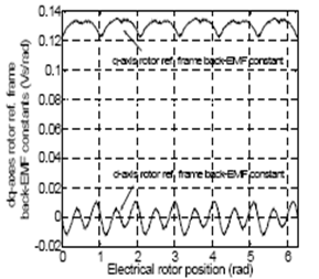
Fig.
3. Actual q– and d–axis rotor reference frame back-EMF constants versus
electrical rotor position and

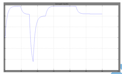
Fig.4.
Steady-state and transient behavior of the experimental (a) q–axis
stator current, (b) d–axis stator current, (c) estimated electromagnetic
torque and (d) ba–ca frame currents when under 0.5 N·m load torque.

Fig.
5. Experimental indirectly controlled stator flux linkage trajectory under the
sensorless three-phase conduction DTC of a BLDC motor drive when at 0.5 N·m load torque.

Fig.
6. Steady-state and transient behavior of the actual and estimated electrical
rotor positions from top to bottom, respectively under 0.5 N·m load torque.
CONCLUSION:
This
study has successfully demonstrated application of the proposed position
sensorless three-phase conduction direct torque control (DTC) scheme for BLDC
motor drives. It is shown that the BLDC motor could also operate in the field weakening
field weakening region by properly selecting the d–axis current reference
in the proposed DTC scheme. First, practically available actual two
line-to-line back-EMF constants (%"# and %$#) versus electrical rotor position
are obtained using generator test and converted to the dq frame
equivalents usingthe new Line-to-Line Park Transformation in which only two input
variables are required. Then, they are used in the torque estimation algorithm.
Electrical rotor position required in the torque estimation is obtained using
winding inductance, stationary reference frame currents and stator flux
linkages. Since the actual back-EMF waveforms are used in the torque
estimation, low-frequency torque oscillations can be reduced convincingly
compared to the one with the ideal trapezoidal waveforms having 120 electrical
degree flat top. A look-up table for the three-phase voltage vector selection
is designed similar to a DTC of PMSM drive to provide fast torque and flux
control. Because the actual rotor flux linkage is not sinusoidal, stator flux
control with constant reference is not viable anymore. Therefore, indirect
stator flux control is performed by controlling the flux related d–axis
current using bang-bang (hysteresis) control which provides acceptable control
of time-varying signals (reference and/or feedback) quite well. Since the
proposed DTC scheme does not involve any PWM strategies, PI controllers as well
as inverse Park and Clarke Transformations to drive the motor, much simpler overall
control is achieved.
REFERENCES:
[1]
I. Takahashi and T. Noguchi, “A new quick-response and high efficiency control
strategies of an induction motor,” IEEE Trans. Ind. Appl., vol.
22, no. 5, pp. 820–827, Sep./Oct. 1986.
[2]
M. Depenbrock, “Direct self-control of inverter-fed induction machine,” IEEE
Trans. Power Electron., vol. 3, no. 4, pp. 420–429, Oct. 1988.
[3]
L. Zhong, M. F. Rahman, W. Y. Hu, and K. W. Lim, “Analysis of direct torque
control in permanent magnet synchronous motor drives,” IEEE Trans. Power
Electron., vol. 12, no. 3, pp. 528–536, May 1997.
[4]
Y. Liu, Z. Q. Zhu, and D. Howe, “Direct torque control of brushless dc drives
with reduced torque ripple,” IEEE Trans. Ind. Appl., vol. 41, no. 2, pp.
599–608, Mar./Apr. 2005.
[5]
S. B. Ozturk and H. A. Toliyat, “Direct torque control of brushless dc motor
with non-sinusoidal back-EMF,” in Proc. IEEE-IEMDC Biennial Meeting,
Antalya, Turkey, May 3-5, 2007.