asokatechnologies@gmail.com 09347143789/09949240245

Search This Blog

Sunday 24 May 2020

Optimization techniques to enhance the performance of induction motor drives: A review


ABSTRACT:  
Induction motor (IM) drives, specifically the three-phase IMs, are a nonlinear system that are difficult to explain theoretically because of their sudden changes in load or speed conditions. Thus, an advanced controller is needed to enhance IM performance. Among numerous control techniques, fuzzy logic controller (FLC) has increasing popularity in designing complex IM control system due to their simplicity and adaptability. However, the performance of FLCs depends on rules and membership functions (MFs), which are determined by a trial and- error procedure. The main objective of this paper is to present a critical review on the control and optimization techniques for solving the problems and enhancing the performance of IM drives. A detailed study on the control of variable speed drive, such as scalar and vector, is investigated. The scalar control functions of speed and V/f control are explained in an open- and closed-loop IM drive. The operation, advantages, and limitations of the direct and indirect field-oriented controls of vector control are also demonstrated in controlling the IM drive. A comprehensive review of the different types of optimization techniques for IM drive applications is highlighted. The rigorous review indicates that existing optimization algorithms in conventional controller and FLC can be used for IM drive. However, some problems still exist in achieving the best MF and suitable parameters for IM drive control. The objective of this review also highlights several factors, challenges, and problems of the conventional controller and FLC of the IM drive. Accordingly, the review provides some suggestions on the optimized control for the research and development of future IM drives. All the highlighted insights and recommendations of this review will hopefully lead to increasing efforts toward the development of advanced IM drive controllers for future applications.
KEYWORDS:
1.      Induction motor drive
2.      Optimization algorithms
3.      Scalar control
4.      Vector control
5.      Fuzzy logic controller
SOFTWARE: MATLAB/SIMULINK

BLOCK DIAGRAM:


Fig. 1. Architecture of the IM control system.

 CLOSED-LOOP OF SCALAR CONTROL FOR IM DRIVE:


Fig. 2. Closed-loop of scalar control for IM drive.

BLOCK DIAGRAM OF DFOC FOR IM DRIVE


Fig. 3. Block diagram of DFOC for IM drive.
BLOCK DIAGRAM OF IFOC FOR IM DRIVE


Fig. 4. Block diagram of IFOC for IM drive.

 BLOCK DIAGRAM OF DTC FOR IM DRIVE


Fig.5 Block diagram of DTC for IM drive


OPTIMIZATION TECHNIQUE BASED ON PID SPEED CONTROLLER FOR SCALAR CONTROL


Fig. 6. Optimization technique based on PID speed controller for scalar control


OPTIMIZATION TECHNIQUE BASED ON PID CONTROLLERS FOR (A) DFOC AND (B) IFOC


(a)


(b)

Fig. 7. Optimization technique based on PID controllers for (a) DFOC and (b) IFOC.


OPTIMIZATION TECHNIQUE BASED ON FUZZY LOGIC SPEED CONTROLLER FOR SCALAR CONTROL.


Fig. 8. Optimization technique based on fuzzy logic speed controller for scalar control.


OPTIMIZATION TECHNIQUE BASED ON FLC CONTROLLERS FOR (A) DFOC AND (B) IFOC.


(a)


(b)

Fig. 9. Optimization technique based on FLC controllers for (a) DFOC and (b) IFOC.
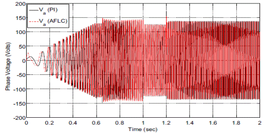
CONCLUSION:
In this paper, an Indirect Field-Oriented Control (IFOC) scheme for a drive system of three-phase induction motor is effectively investigated and validated using various simulation results in Matlab/Simulink. The performance of proposed controller is verified by introducing variation in speed and load torque. Simulation results demonstrate that PI has sluggish response compared to AFLC. In all load torque variations, the proposed AFLC shows robustness and continues to track the reference with small steady-state error. Moreover, AFLC based on LM is robust to model parameter variations, load variations and less sensitive to uncertainties and disturbances. The proposed scheme verifies superior and smoother performance with improved dynamic response.  Furthermore, the effectiveness of proposed AFLC is evaluated and justified from performance indices IAE, ISE and ITAE.
REFERENCES:
1. Leonhard W (1996) Controlled AC drives, a successful transfer from ideas to industrial practice. Control Eng Pract 4(7):897–908
2. Fitzgerald AE,KingsleyCU, StephenD(1990) Electricmachinery, 5th edn. McGraw-Hill, New York
3. Marino R, Peresada S, Valigi P (1993) Adaptive input-output linearizing  control of induction motors. IEEE Trans Autom Cont 38(2):208–221
4. Leonhard W (1985) Control of electrical drives. Springer-, Berlin 
5. HeinemannG(1989) Comparison of several control schemes for ac induction motors. In: Proceedings of European Power Electronics Conference (EPE’89), pp 843–844


Indirect field-oriented control of induction motor drive based on adaptive fuzzy logic controller


ABSTRACT:  
Recently, Asynchronous Motors are extensively used as workhorse in a multitude of industrial and high performance applications. Induction Motors (IM) have wide applications in today’s industry because of their robustness and low maintenance. A smart and fast speed control system, however, is in most cases a prerequisite for most applications. This work presents a smart control system for IM using an Adaptive Fuzzy Logic Controller (AFLC) based on the Levenberg–Marquardt algorithm. A synchronously rotating reference frame is used to model IM. To achieve maximum efficiency and torque of the IM, speed control was found to be one of the most challenging issues. Indirect Field-Oriented Control (IFOC) or Indirect Vector Control techniques with robust AFLC offer remarkable speed control with high dynamic response. Computer simulation results using MATLAB/Simulink® Toolbox are described and examined in this study for conventional PI and AFLC. AFLC presents robustness as regards overshoot, undershoot, rise time, fall time, and transient oscillation for speed  variation of IFOC IM drive in comparison with classical PI. Moreover, load disturbance rejection capability for the designed control scheme is also verified with the AFL controller.
KEYWORDS:
1.      Induction Motor (IM)
2.      Indirect Field-Oriented Control (IFOC)
3.       Pulse Width Modulation (PWM)

SOFTWARE: MATLAB/SIMULINK
BLOCK DIAGRAM:


Fig. 1 Proposed system block diagram using AFLC

EXPERIMENTAL RESULTS:


Fig. 2 dq axis stator currents  for both AFLC & PI controller


Fig. 3 Stator phase voltage for both AFLC & PI controller


Fig. 4 Stator phase current for both AFLC & PI controller


Fig. 5 Rotor speed under variable load torque, a comparison of AFLC based on LM & PI


Fig. 6 dq-axis stator currents for both AFLC & PI controller


Fig. 7 Stator phase voltage for both AFLC & PI controller


Fig. 8 Stator phase current for both AFLC & PI controller


Fig. 9 Rotor speed under variable load torque, a comparison of AFLC based on LM & PI


Fig. 10 dq-axis stator currents for both AFLC & PI controller


Fig. 11 Stator phase voltage for both AFLC & PI controller


Fig. 12 Stator phase current for both AFLC & PI controller

 CONCLUSION:
In this paper, an Indirect Field-Oriented Control (IFOC) scheme for a drive system of three-phase induction motor is effectively investigated and validated using various simulation results in Matlab/Simulink. The performance of proposed controller is verified by introducing variation in speed and load torque. Simulation results demonstrate that PI has sluggish response compared to AFLC. In all load torque variations, the proposed AFLC shows robustness and continues to track the reference with small steady-state error. Moreover, AFLC based on LM is robust to model parameter variations, load variations and less sensitive to uncertainties and disturbances. The proposed scheme verifies superior and smoother performance with improved dynamic response.  Furthermore, the effectiveness of proposed AFLC is evaluated  and justified from performance indices IAE, ISE and ITAE.
REFERENCES:
1. Leonhard W (1996) Controlled AC drives, a successful transfer from ideas to industrial practice. Control Eng Pract 4(7):897–908
2. Fitzgerald AE,KingsleyCU, StephenD(1990) Electricmachinery, 5th edn. McGraw-Hill, New York
3. Marino R, Peresada S, Valigi P (1993) Adaptive input-output linearizing  control of induction motors. IEEE Trans Autom Cont 38(2):208–221
4. Leonhard W (1985) Control of electrical drives. Springer-, Berlin 
5. HeinemannG(1989) Comparison of several control schemes for ac induction motors. In: Proceedings of European Power Electronics Conference (EPE’89), pp 843–844


Wednesday 20 May 2020

A New Switched-Capacitor Five-Level Inverter Suitable for Transformerless Grid-Connected Applications


ABSTRACT:  

 Transformerless grid-connected inverters have been extensively popular in renewable energy-based applications owing to some interesting features like higher efficiency, reasonable cost and acceptable power density. The major concern of such converters is the leakage current problem and also the step-down feature of the output voltage which causes a costly operation for a single stage energy conversion system. A new five-level transformerless inverter topology is presented in this study, which is able to boost the value of the input voltage and can remove the leakage current problem through a common-grounded architecture. Here, providing the five-level of the output voltage with only six power switches is facilitated through the series-parallel switching of a switched-capacitor module. Regarding this switching conversion, the self- voltage balancing of the integrated capacitors over a full cycle of the grid’s frequency can be acquired. Additionally, to inject a tightly controlled current to the local grid, a peak current controller-based technique is employed, which can regulate both the active and reactive power support modes. Theoretical analyses besides some experimental results are also given to corroborate the correct performance of the proposed topology.
KEYWORDS:

1.      Transformerless inverter
2.      Common ground type
3.      Switched Capacitor module and Grid connected applications

SOFTWARE: MATLAB/SIMULINK

BLOCK DIAGRAM:


Fig. 1. The overall block diagram of the controlled system.

 EXPERIMENTAL RESULTS:


Fig. 2. (a) Inverter’s output voltage (200 V/div) and the injected grid’s current (4 A/div) (b) Inverter’s output voltage (200V/div) and the local’s grid voltage (200V/div) (c) Injected grid’s current (4A/div) and local grid’s voltage (100 V/div) (d) the voltage across (200V/div) and the voltage across (100V/div). 2 C 1 C


Fig. 3.(a) The leading injected grid’s current (4 A/div) with the grid’s voltage (100 V/div) (b) The lagging injected grid current (4 A/div) with the grid’s voltage (100 V/div) (c) The grid’s voltage (blue trace) (200 V/div) and the injected grid current (green trace) (4 A/div) under the step-change of the PF from unity to a non-unity one.

Fig. 4. The measured current waveform through 1 C and 2 C (4 A/div).


Fig. 5. The measured PIV of power switches; (100 V/div) and (200 V/div). 1 2 / SS4 5 6 / / S S S


Fig. 6. The current stress waveforms of (a) (5 A/div) and (5 A/div), (b) (5 A/div), and (2 A/div) (c) (2 A/div) and (5 A/div). 1 S 2 S 3 S 6 S 4 S 5 S


Fig. 7. Dynamic performance of the proposed system under a voltage sag in the local grid’s voltage (a) The injected current (blue trace) (4 A/div) and the local grid’s voltage (red trace) (200 V/div) (b) The injected current (4 A/div) and the voltage across C1 (100 V/div) (c) The injected current (4 A/div) and the voltage across C2 (200 V/div).


CONCLUSION:
A new five-level SC-based transformerless grid-connected inverter has been presented in this study. The proposed topology is able to remove the leakage current concern with a common-grounded architecture. Also, with the reasonable number of active and passive involved elements, it offers a two times voltage boosting feature that makes it suitable for PV string applications. A PCC-based strategy has also been employed in following to regulate the value of the injected current. Details of such a controlled system besides some analysis as for the conduction losses, the design guidelines and voltage/current stresses of the switches were also given to further explore the performance of the proposed topology. Finally, a comprehensive comparative study alongside the experimental results of a 590 W built prototype have been presented to confirm the superiority and accurate operation of the proposed system.
REFERENCES:
[1] S. B. Kjaer, J. K. Pedersen, and F. Blaabjerg, “A review of single-phase grid-connected inverters for photovoltaic modules,” IEEE Trans. Ind. Applicat., vol. 41, no. 5, pp. 1292-1306, Sep./Oct. 2005.
[2] M. Islam, S. Mekhilef, M. Hasan, “Single phase transformerless inverter topologies for grid-tied photovoltaic system: A review,” Renewable and Sustainable Energy Reviews, vol. 45, pp. 69-86, 2015.
[3] H. Xiao and S. Xie, “Leakage current analytical model and application in single-phase transformerless photovoltaic grid-connected inverter,” IEEE Trans. Electromagn. Compat., vol. 52, no. 4, pp. 902–913, Nov. 2010.
[4] D. Meneses, F. Blaabjerg, Ó Garcia, and Jo ´ se A. Cobos, “Review ´and comparison of step-up transformerless topologies for photovoltaic AC-module application,” IEEE Trans. Power Electron., vol. 28, no. 6, pp. 2649–2663, Jun. 2013.
[5] S. Saridakis, E. Koutroulis, F. Blaabjerg, “Optimization of SiC-Based H5 and Conergy-NPC Transformerless PV Inverters,” IEEE Emerg. Select. Topics Power Electron., vol. 3, no. 2, pp. 555-567, June. 2015.