ABSTRACT:
Excessive use of nonlinear and time varying devices results
in harmonic currents in the secondary distribution system. The suppression of
harmonics is a dominant issue and one of the practical ways to compensate
harmonics is shunt active power filter (SAPF). The core part of the SAPF is
control techniques used for reference current generation. This paper presents a
comprehensive study of three control strategies namely instantaneous reactive
power (p – q) theory, synchronous reference frame (SRF) theory and
instantaneous active and reactive current (id - iq) component method for SAPF
in a three phase three wire distribution system. These three control methods
aims to compensate harmonics, reactive power and load unbalance under
sinusoidal balanced supply voltage conditions. Simulation results present a
relative investigation of three control techniques based on current THD and
load unbalance.
KEYWORDS:
1.
Harmonics
2.
Hysteresis band current control (HBCC)
3.
Id - iq method
4.
Nonlinear loads
5.
P – q theory
6.
Shunt active power filter
7.
SRF theory
SOFTWARE: MATLAB/SIMULINK
BLOCK DIAGRAM:

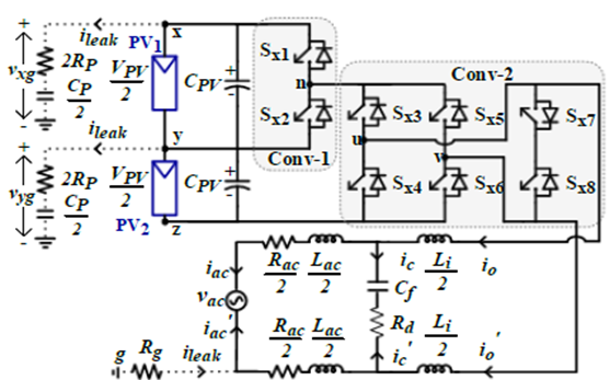
Fig.
1. SAPF connected to distribution grid

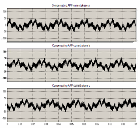
Fig.
2. Simulation results of SAPF with p-q theory under nonlinear balanced
load
(a) Source voltage (b) Load current (c) Source current after filtering
(d)
Compensation current.

Fig.
3. Simulation results of SAPF with id-iq method under nonlinear
balanced
load (a) Source current after filtering (b) Compensation current

Fig.
4. Simulation results of SAPF with id-iq method under nonlinear
unbalanced
load (a) Source voltage (b) Load current (c) Source current
after
filtering (d) Compensation current.

Fig.
5. Dynamic performance of SAPF during load change with id-iq method
(a)
Load
current (b) Source current (c) Compensation current.


Fig.
6. (a) Source voltage (V) and load current (A) (b) Source voltage (V)
and
source current (A) (c) Compensation current (d) Reactive power
demand
of the load (e) Reactive power supplied by the SAPF (f)
Reactive
power supplied by the source.
CONCLUSION:
The
harmonic distortions exist in the distribution system due to the massive use of
power electronic based nonlinear loads. Harmonic distortions can result in
serious problems such as increase in current, reactive VAs, VAs, power factor reduction
and increase in losses. The SAPF with three control strategies viz. p-q theory,
SRF theory and id-iq method has been studied in this paper. The simulation has
been carried out for different load scenarios and the THD, percentage of individual
dominant harmonics has also observed. From the simulation analysis, it is
observed that the SAPF giving quite reasonably good performance in compensating
harmonics, reactive power and load unbalance. Among the three control techniques,
it is noticed that the id-iq method gives reasonably better performance in terms
of current THD.
[1]
S. Rahmani, N. Mendalek, and K. Al-Haddad, "Experimental design of a nonlinear
control technique for three-phase shunt active power filter," IEEE Trans.
Ind. Electron, vol. 57, no. 10, pp. 3364-3375, Oct. 2010.
[2]
IEEE Recommended Practice and Requirements for Harmonic Control in Electric
Power Systems - Redline," IEEE Std 519-2014 (Revision of IEEE Std
519-1992) - Redline , pp.1-213, June 11 2014.
[3]
S. Senini and P. J. Wolfs, “Hybrid active filter for harmonically unbalanced
three phase three wire railway traction loads,” IEEE Trans. Power Electron.,
vol. 15, no. 4, pp. 702–710, Jul. 2000.
[4]
S. Rahmani, K. Al-Haddad, H. Y. Kanaan, and B. Singh,
“Implementation
and simulation of a modified PWM with two current control techniques applied to
a single-phase shunt hybrid power filter,” Proc. Inst. Elect. Eng. Electr.
Power Appl., vol. 153, no. 3, pp. 317–326, May 2006.
[5]
B. Singh, K. Al-Haddad, and A. Chandra, "A review of active filters for power
quality improvement," IEEE Trans. Ind. Electron, vol. 46, no. 5, pp.
960-971, Oct 1999.