asokatechnologies@gmail.com 09347143789/09949240245

Search This Blog

Friday, 14 November 2014

A High-Efficiency Wide-Input-Voltage Range Switched Capacitor Point-of-Load DC–DC Converter

A High-Efficiency Wide-Input-Voltage Range Switched Capacitor Point-of-Load DC–DC Converter

ABSTRACT:

The traditional inductor-based buck converter has been the default design for switched-mode voltage regulators for decades. Switched capacitor (SC) dc–dc converters, on the other hand, have traditionally been used in low-power (<10 mW) and low conversion ratio (<4:1) applications where neither regulation nor efficiency is critical. This study encompasses the complete successful design, fabrication, and test of a CMOS-based SC dc–dc converter, addressing the ubiquitous 12–1.5 V board mounted point-of-load application. In particular, the circuit developed in this study attains higher efficiency (92% peak, and >80% over a load range of 5 mA to 1 A) than surveyed competitive buck converters, while requiring less board area and less costly passive components. The topology and controller enable a wide input range of 7.5–13.5 V. Controls based on feedback and feed forward provide tight regulation under worst case line and load step conditions. This study shows that the SC converter can outperform the buck
 converter, and thus, the scope of SC converter application can and should be expanded.

KEYWORDS:

1.      DC-DC power converters
2.       switched capacitor circuits
3.      switched-mode power supply

SOFTWARE: MATLAB/SIMULINK

BLOCK DIAGRAM:


 Fig. 1. Overall block diagram of the controller.

CONCLUSION:

The traditional inductor-based buck converter has been the default design for switched-mode voltage regulators for decades. Switched capacitor (SC) dc–dc converters, on the other hand, have traditionally been used in low-power (<10 mW) and low conversion ratio (<4:1) applications where neither regulation nor efficiency is critical. This study encompasses the complete successful design, fabrication, and test of a CMOS-based SC dc–dc converter, addressing the ubiquitous 12–1.5 V board mounted point-of-load application. In particular, the circuit developed in this study attains higher efficiency (92% peak, and >80% over a load range of 5 mA to 1 A) than surveyed competitive buck converters, while requiring less board area and less costly passive components. The topology and controller enable a wide input range of 7.5–13.5 V. Controls based on feedback and feed forward provide tight regulation under worst case line and load step conditions. This study shows that the SC converter can outperform the buck converter, and thus, the scope of SC converter application can and should be expanded.

REFERENCES:

[1] M. Seeman and S. Sanders, “Analysis and optimization of switched capacitor dc–dc converters,” IEEE Trans. Power Electron., vol. 23, no. 2, pp. 841–851, Mar. 2008.
[2] M. Seeman,V.Ng, H.-P. Le,M. John, E. Aton, and S. Sanders, “Acomparative analysis of switched-capacitor and inductor-based dc–dc conversion technologies,” in Proc. IEEE Workshop Control Model. Power Electron. (COMPEL), Jun. 2010.
[3] M. Seeman, “A design methodology for switched-capacitor dc-dc converters,” Ph.D. dissertation, UC Berkeley, Berkeley, CA, May 2009.
[4] High Efficiency, 250 mA Step-Down Charge Pump, Texas Instruments (TPS60503), Dallas, TX, 2002.
[5] 500 mA High Efficiency, Low Noise, Inductor-Less Step-Down DC/DC Converter, Linear Technology (LTC3251), Milpitas, CA, 2003.

Wednesday, 12 November 2014

Fuzzy-Logic-Controller-Based SEPIC Converter for Maximum Power Point Tracking

Fuzzy-Logic-Controller-Based SEPIC Converter for
Maximum Power Point Tracking

ABSTRACT:

This paper presents a fuzzy logic controller (FLC)-based single-ended primary-inductor converter (SEPIC) for maximum power point tracking (MPPT) operation of a photovoltaic (PV) system. The FLC proposed presents that the convergent distribution of the membership function offers faster response than the symmetrically distributed membership functions. The fuzzy controller for the SEPIC MPPT scheme shows high precision in current transition and keeps the voltage without any changes, in the variable-load case, represented in small steady-state error and small overshoot. The proposed scheme ensures optimal use of PV array and proves its efficacy in variable load conditions, unity, and lagging power factor at the inverter output (load) side. The real-time implementation of the MPPT SEPIC converter is done by a digital signal processor (DSP), i.e., TMS320F28335. The performance of the converter is tested in both simulation and experiment at different operating conditions. The performance of the proposed FLC-based MPPT operation of SEPIC converter is compared to that of the conventional proportional–integral (PI)-based SEPIC converter. The results show that the proposed FLC-based MPPT scheme for SEPIC can accurately track the reference signal and transfer power around 4.8% more than the conventional PI-based system.

KEYWORDS:
1.     DC–DC power converters
2.     Fuzzy control
3.     Photovoltaic(PV) cells
4.     Proportional–integral (PI) controller
5.     Real-time system.


SOFTWARE: MATLAB/SIMULINK

BLOCK DIAGRAM:


          Fig. 1. Overall control scheme for the proposed FLC-based MPPT scheme for the SEPIC converter.


CONCLUSION:

An FLC-based MPPT scheme for the SEPIC converter and inverter system for PV power applications has been presented in this paper. A prototype SEPIC converter-based PV inverter system has also been built in the laboratory. The DSP board TMS320F28335 is used for real-time implementation of the proposed FLC and MPPT control algorithms. The performance of the proposed controller has been found better than that of the conventional PI-based converters. Furthermore, as compared to the conventional multilevel inverter, experimental results indicated that the proposed FLC scheme can provide a better THD level at the inverter output. Thus, it reduces the cost of the inverter and the associated complexity in control algorithms. Therefore, the proposed FLC-based MPPT scheme for the SEPIC converter could be a potential candidate for real-time PV inverter applications under variable load conditions.

REFERENCES:

[1] K.M. Tsang andW. L. Chan, “Fast acting regenerative DC electronic load based on a SEPIC converter,” IEEE Trans. Power Electron., vol. 27, no. 1, pp. 269–275, Jan. 2012.
[2] S. J. Chiang, H.-J. Shieh, and M.-C. Chen, “Modeling and control of PV charger system with SEPIC converter,” IEEE Trans. Ind. Electron., vol. 56, no. 11, pp. 4344–4353, Nov. 2009.
[3] M. G. Umamaheswari, G. Uma, and K. M. Vijayalakshmi, “Design and implementation of reduced-order sliding mode controller for higher-order power factor correction converters,” IET Power Electron., vol. 4, no. 9, pp. 984–992, Nov. 2011.
[4] A. A. Fardoun, E. H. Ismail, A. J. Sabzali, and M. A. Al-Saffar, “New efficient bridgeless Cuk rectifiers for PFC applications,” IEEE Trans. Power Electron., vol. 27, no. 7, pp. 3292–3301, Jul. 2012.


Friday, 7 November 2014

A Novel Three-Phase Three-Leg AC/AC Converter Using Nine IGBTs

A Novel Three-Phase Three-Leg AC/AC Converter Using Nine IGBTs

ABSTRACT:
This paper proposes a novel three-phase nine-switch ac/ac converter topology. This converter features sinusoidal inputs and outputs, unity input power factor, and more importantly, low manufacturing cost due to its reduced number of active switches. The operating principle of the converter is elaborated; its modulation schemes are discussed. Simulated semiconductor loss analysis and comparison with the back-to-back two-level voltage source converter are presented. Finally, experimental results from a 5-kVA prototype system are provided to verify the validity of the proposed topology.

KEYWORDS:

1.      AC/AC converter
2.       pulse width modulation (PWM)
3.      reduced switch count topology


SOFTWARE: MATLAB/SIMULINK


CIRCUIT DIAGRAM:


                                                        Fig: 1 B2B 2L-VSC.


 CONCLUSION:
A novel nine-switch PWMac/ac converter topology was proposed in this paper. The topology uses only nine IGBT devices for ac to ac conversion through a quasi dc-link circuit. Compared with the conventional back-to-back PWM VSC using 12 switches and the matrix converter that uses 18, the number of switches in the proposed converter is reduced by 33% and 50%, respectively. The proposed converter features sinusoidal inputs and outputs, unity input power factor, and low manufacturing cost. The operating principle of the converter was elaborated, and modulation schemes for constant and VF operations were developed. Simulation results including a semiconductor loss analysis and comparison were provided, which reveal that the proposed converter, while working in CF mode, has an overall higher efficiency than the B2B 2L-VSC at the expense of uneven loss distribution. However, the VF-mode version requires IGBT devices with higher ratings and dissipates significantly higher losses, and thus, is not as attractive as its counterpart. Experimental verification is carried out on a 5-kVA prototype system.

REFERENCES:

[1] B. Wu, High-power Converters and AC Drives. Piscataway, NJ: IEEE/Wiley, 2006.
[2] B. Singh, B. N. Singh, A. Chandra, K. Al-Haddad, A. Pandey, and D. P. Kothari, “A review of three-phase improved power quality AC– DC converters,” IEEE Trans. Ind. Electron., vol. 51, no. 3, pp. 641–660, Jun. 2004.
[3] F. Blaabjerg, S. Freysson, H. H. Hansen, and S. Hansen, “A new optimized space-vector modulation strategy for a component-minimized Voltage source inverter,” IEEE Trans. Power Electron., vol. 12, no. 4, pp. 704–714, Jul. 1997.

[4] R. L. A. Ribeiro, C. B. Jacobina, E. R. C. da Silva, and A. M. N. Lima, “AC/AC converter with four switch three phase structures,” in Proc. IEEE PESC, 1996, vol. 1, pp. 134–139.

Tuesday, 4 November 2014

A Novel Zero-Voltage-Switching PWM Full Bridge Converter

A Novel Zero-Voltage-Switching PWM Full Bridge Converter


ABSTRACT

Introducing resonant inductance and clamping diodes into the full-bridge converter can eliminate the voltage oscillation across the rectifier diodes and increase the load range for zero-voltage-switching (ZVS) achievement. The resonant inductance is shorted and its current keeps constant when the clamping diode is conducting, and the clamping diode is hard turned-off, causing significant reverse recovery loss if the output filter inductance is relatively larger. This paper improves the full-bridge converter by introducing a reset winding in series with the resonant inductance to make the clamping diode current decay rapidly when it conducts. The reset winding not only reduces the conduction losses, but also makes the clamping diodes naturally turn-off and avoids the reverse recovery. The operation principle of the proposed converter is analyzed. The design of the turns ratio of transformer is discussed. A 1 kW prototype converter is built to verify the operation principle and the experimental results are also demonstrated.

KEYWORDS
      1.  Clamping diodes
        2.    Full bridge converter
        3.    Reset winding
        4.    Zero-voltage-switching (ZVS)

SOFTWARE: MATLAB/SIMULINK


BLOCK DIAGRAM:

Fig.1. Proposed ZVS PWM full bridge converter.(a) Tr_ lag  type. (b) Trlead  type.


CONCLUSION:

A new ZVS PWM full-bridge converter is proposed in this   paper, it employs an additional reset winding to make the clamping diode current decay rapidly when the clamping diode conducts, thus the conduction losses of the clamping diodes, the leading switches and the resonant inductance are reduced and the conversion efficiency can be increased. In the meanwhile, the clamping diodes can be turned off naturally without reverse recovery over the whole input voltage range, and the output filter inductance can be designed to be large to obtain small current ripple, leading to reduced filter capacitance. Compared with the traditional full bridge converter [14]–[16], the proposed circuit provides another simple and effective approach to avoid the reverse recovery of the clamping diodes. The operation principle, features and comparisons are illustrated. The Experimental results from the prototype are shown to verify the feasibility of the proposed converter.

REFERENCES:

[1] X. Ruan and Y. Yan, “Soft-switching techniques for pwm full bridge converters,” in Proc. IEEE Power Electron. Spec. Conf. (PESC’00), 2000, pp. 634–639.
[2] D. M. Sable and F. C. Lee, “The operation of a full-Bridge, zero voltage- switched pwm converter,” in Proc. Virginia Power Electron. Center (VPEC’89), 1989, pp. 92–97.
[3] J. A. Sabate, V. Vlatkovic, R. B. Ridley, F. C. Lee, and B. H. Cho, “Design considerations for high-voltage, high power full-bridge zero voltage- switched pwm converter,” in Proc. IEEE Appl. Power Electron. Conf. (APEC’90), 1990, pp. 275–284.

[4] G. C. Hua, F. C. Lee, and M. M. Jovanovic, “An improved zero-voltage-switched pwm converter using a saturable inductor,” in Proc. IEEE Power Electron. Spec. Conf. (PESC’91), 1991, pp. 189–194.

PMSM Speed Sensor less Direct Torque Control Based On EKF

PMSM Speed Sensor less Direct Torque Control Based On EKF


ABSTRACT

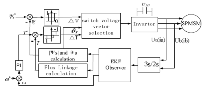
 System with mechanical speed sensor has lower reliability and higher cost. Traditional direct torque control method has disadvantages of big ripples on current and flux linkage and torque. To solve these problems, the Extended Kalman Filter is established to estimate both stator flux linkage and rotor speed. Therefore, speed sensorless direct torque control for surface permanent magnet synchronous motor is realized. Simulation results have shown that the advantage of direct torque control method such as rapid torque response is maintained, at the same time, the system based on EKF is robust to motor parameters and load disturbance. The dynamic and static performances are dramatically improved.

KEYWORDS

1.      Direct torque control
2.      Permanent magnet
3.      Synchronous motor (PMSM)
4.      Extended kalman filter (EKF)
5.      Stator flux linkage observation
6.      Speed sensorless control

SOFTWARE: MATLAB/SIMULINK

BLOCK DIAGRAM:


Figure 1. Schematic diagram of speed sensorless DTC control for SPMSM based on EKF


CONCLUSION:

Speed sensorless DTC control based on EKF for SPMSM is proposed. For a relatively accurate SPMSM model, flux linkage and rotor speed and rotor position can be estimated more precisely by EKF algorithm. Ripples on torque and stator flux are reduced. The motor start problems are solved as EKF do not need accurate initial rotor position information to achieve observer stability convergence. DTC control for PMSM based on EKF has just begun. Many places are imperfect and need for further study.


REFERENCES:

[1] L.Zhong, M.F.Rahman, W.Y. Hu , K.W.Lim, “Analysis of direct torque control in permanent magnet synchronous motor drives,” IEEE Trans. On Power Electronics, 1997, 13(5), pp:528-536.
[2] Jun Hu, Bin Wu. “New integration algorithms for estimating motor flux over a wide speed range,” IEEE Trans. on Power Electronics, 1998, 13(5),pp:969-977.
[3] Cenwei Shi, Jianqi Qiu, Mengjia Jin, “Study on the performance of different direct torque control methods for permanent magnet synchronous machines,” Proceeding of the Csee, 2005, 25(16),pp:141- 146.
[4] Limei Wang, Yanping Gao. “Direct torque control for permanent magnet synchronous motor based on space voltage vector pulse width modulation,” Journal of Shenyang University of Technology, 2007,29(6), pp:613-617.
[5] Zhiwu Huang, Yi Li, Xiaohong Nian, “Simulation of direct torque control based on modified integrator,” Computer Simulation, 2007,24(02),pp:149-152.


Direct Torque Control of Induction Motors with Fuzzy Minimization Torque Ripple

Direct Torque Control of Induction Motors with Fuzzy Minimization Torque Ripple

ABSTRACT

Direct torque control (DTC) is a new method of induction motor control. The key issue of the DTC is the strategy of selecting proper stator voltage vectors to force stator flux and developed torque within a prescribed band. Due to the nature of hysteresis control adopted in DTC, there is no difference in control action between a larger torque error and a small one. It is better to divide the torque error into different intervals and give different control voltages for each of them. To deal with this issue a fuzzy controller has been introduced. But, because the number of rules is too high some problems arise and the speed of fuzzy reasoning will be affected. In this paper, a comparison between a new fuzzy direct-torque control (DTFC) with space vector modulation (SVM) is made. The principle and a tuning procedure of the fuzzy direct torque control scheme are discussed. The simulation results, which illustrate the performance of the proposed control scheme in comparison with the fuzzy hysteresis connected of DTC scheme are given.

KEYWORDS

1.      Induction machine
2.      Direct torque control
3.      Fuzzy logic
4.      Space vector modulation

SOFTWARE: MATLAB/SIMULINK

BLOCK DIAGRAM:

Fig. 1. A novel direct torque control scheme for ac motor drives (DTC) with fuzzy hysteresis and space vector modulation

CONCLUSION:

In this paper, a fuzzy direct torque control with space vector modulation is analyzed in comparison to fuzzy hysteresis connected of DTC. The results obtained by numerical simulation are given. In short, the advantages of proposed fuzzy direct torque control using space vector modulation technique in comparison with a fuzzy hysteresis of DTC are the following:
– Reduced torque and flux distortion;
– Constant switching frequency thanks to apply SVM;
– Fast torque response because of the use of fuzzy controller;
– Lower sampling time;
– No problems during Low-speed operation;
– No current and torque distortion caused by sector changes.

REFERENCES:

[1] Casadei, D., serra, G., Tani, A, «Performance analysis of a DTC control scheme for induction motor in the low speed range», in proceeding of EPE, (1997), p.3.700-3.704, Trondheim.
[2] Depenbrok. M, «Direct self-control (DSC) of inverter fed induction machine», In: IEEE Trans. On PE (1988), Vol. PE-3, No4, October 1988, p 420-429.
[3] A. Cataliotti, G. Poma: “A Fuzzy approach for easy and robust control of an induction motor”. EPE 97, pp 2.421-2.425, 1997.
[4] J. R G Schonfield,”Direct torque control-DTC", ABB Industrial Systems Ltd.
[5] Ned Gulley, J.-S. Roger Jang: Fuzzy Logic Toolbox for Use With Matlab". The Math Works inc, Natick, Mass, 1996.


Study On Speed Sensorless SVM-DTC System Of PMSM

Study On Speed Sensorless SVM-DTC System Of PMSM

ABSTRACT

A novel speed sensorless direct torque control system-SVM-DTC of permanent magnet synchronous motor (PMSM) based on SVM and MRAS is presented. In this paper the various components of the speed sensorless SVM-DTC and the principle of realization are discussed in detail. Finally the simulation results with the application of MATLAB/SIMULINK show that the speed identification algorithm is accurate and of robustness, moreover, the whole control system has good static and dynamic performances.

KEYWORDS:

1.      Permanent magnet synchronous motor (PMSM)
2.      Space Vector Modulation (SVM)
3.      Direct torque control (DTC)
4.      Model reference adaptive system (MRAS)

SOFTWARE: MATLAB/SIMULINK

BLOCK DIAGRAM:

Fig.1. Speed-sensor less SVM-DTC diagram.


CONCLUSION:

In this paper, the speed sensorless SVM-DTC system based on SVM and MRAS is presented and the control system has a clear control principle and structure. Simulation results show that the speed identification algorithm can estimate accurately the real speed and has robustness to varying of stator resistor. Moreover the speed sensorless SVM-DTC system has good static and dynamic performance.

REFERENCES:

[1] Yen-Shin Lai, Jian-Ho Chen..A New Approach to Direct Torque Control of Induction Motor Drives for Constant Inverter Switching Frequency and Torque Ripple Reduction[J],IEEE Transactions on Energy Conversion,2001,16(3),220-227
[2] Liang yan, Li Yongdong. The state of art of sensor-less vector control of PMSM[J]. Electric Drive,2003,33(4):4-9
[3] Young Sam Kim, Sang Kyoon Kim,Young Ahn Kwon.MRAS Based Sensorless Control of Permanent Magnet Synchronous Motor[C]. SICE Annual Conference, Fukui, Japan, 2003:1632-1637
[4] Li Yongdong. AC motor digital control system [M]. Beijing: Machine Press,2002

[5] Li Su. Direct Torque Control of Induction Motor[M]. Beijing: Machine Press,1999