asokatechnologies@gmail.com 09347143789/09949240245

Search This Blog

Friday, 8 July 2022

Assessment and Mitigation of Dynamic Instabilities in Single-Stage Grid-Connected Photovoltaic Systems With Reduced DC-Link Capacitance

ABSTRACT:

Single-stage utility-scale photovoltaic (PV) systems are usually interfaced with the host grid via a centralized voltage-source converter (VSC). Recently, and due to their reliability, the dc-link film capacitors are favored over electrolytic types in grid-connected applications. However, the capacitance per unit volume of film capacitors is significantly smaller than electrolytic capacitors. The overall system stability might be compromised by the reduction of the dc-link capacitance, particularly in PV systems that have a dynamic resistance that varies with operating conditions. Using a detailed small-signal model of the grid-connected PV system, it is shown in this paper that the reduction of the dc-link capacitance interferes with the dynamic resistance of the PV array, which eventually leads to instabilities. The minimum dc-link capacitance that preserves the overall system stability is determined. A simple and effective active compensator is developed to mitigate the instabilities with the reduced dc-link capacitance. Detailed time-domain simulations are presented to validate the analytical results and show the proposed compensator's effectiveness in preserving the system stability.

KEYWORDS:

1.      Active damping

2.      DC-AC power converters

3.      DC-link stabilization

4.      Grid-connected inverters photovoltaic

5.      Single-stage

6.      Small-signal analysis

SOFTWARE: MATLAB/SIMULINK

SCHEMATIC DIAGRAM:


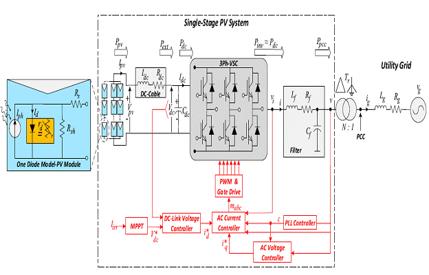
Figure 1. Vector Control Schematic Of The Grid-Connected Vsc.

EXPECTED SIMULATION RESULTS:


Figure 2. Uncompensated System Response Operating In The Cvr, Mpp, And Ccr At T D 0 􀀀 3 S, T D 3 􀀀 4 S, And T D 4 􀀀 7 S, Respectively, As Cdc Decreases From 1 P:U: To 0:6 P:U:


Figure 3. Influence Of Added Active Compensation Loop At T D 1:3s. Under The Ccr Operation.


Figure 4. Compensated System Response Operating In The Cvr, Mpp, And Ccr At T D 0 􀀀 3 S, T D 3 􀀀 4 S, And T D 4 􀀀 7 S, Respectively, As Cdc Decreases From 1 P:U: To 0:6 P:U:


Figure 5. Compensated And Uncompensated Dc-Link Voltage Response To A Single-Phase Ground Fault At T D 1:5 S For 5 Cycles. (A) Under The Ccr And Cdc D 0:6p:U: (B) At Mpp And Cdc D 0:6p:U:


Figure 6. Compensated And Uncompensated Dc-Link Voltage Responses At Cdc D 0:6p:U: Due To The Dc Cable Influence.


Figure 7. Compensated And Uncompensated Dc-Link Voltage Responses At Cdc D 1p:U:


CONCLUSION:

This paper has introduced comprehensive modeling and control of the single-stage grid-connected PV system. The dynamic resistance of the PV arrays is analyzed and defined under different operating regions. It is found that reduced dc-link capacitance affects the dynamic stability of the overall system due to interactions with the dynamic resistance of the PV array. As a result, a new and simple compensator is proposed to stabilize the system with a reduced dc-link capacitance. The small-signal stability analysis of the overall system is performed under different operating conditions. The proposed compensators have the following advantages: 1) it is simple yet effective and can be easily designed using linear analysis tools, 2) it does not affect the steady-state operation of the VSC grid-connected PV system, 3) it improves the damping performance of the dc-link voltage and provides a robust and stable performance at different operating conditions of the PV system, and 4) it facilitates successful low voltage ride-through at different operating conditions.

REFERENCES:

[1] International Renewable Energy Agency. (Mar. 2019). Renewable Capac- ity Statistics. [Online]. Available: https://www.irena.org/-/media/Files/  IRENA/Agency/Publication/2019/Mar/RE_capacity_highlights_2019.pdf

[2] B. Karanayil, V. G. Agelidis, and J. Pou, ``Performance evaluation of three-phase grid-connected photovoltaic inverters using electrolytic or polypropylene _lm capacitors,'' IEEE Trans. Sustain. Energy, vol. 5, no. 4, pp. 1297_1306, Oct. 2014.

[3] F. Blaabjerg, Z. Chen, and S. B. Kjaer, ``Power electronics as efficient interface in dispersed power generation systems,'' IEEE Trans. Power Electron., vol. 19, no. 5, pp. 1184_1194, Sep. 2004.

[4] A. Yazdani, A. R. Di Fazio, H. Ghoddami, M. Russo, M. Kazerani, J. Jatskevich, K. Strunz, S. Leva, and J. A. Martinez, ``Modeling guidelines and a benchmark for power system simulation studies of three-phase single-stage photovoltaic systems,'' IEEE Trans. Power Del., vol. 26, no. 2, pp. 1247_1264, Apr. 2011.

[5] H. Wang and F. Blaabjerg, ``Reliability of capacitors for DC-link applications in power electronic converters_An overview,'' IEEE Trans. Ind. Appl., vol. 50, no. 5, pp. 3569_3578, Oct. 2014.

Wednesday, 6 July 2022

Control of a Three-Phase Power Converter Connected to Unbalanced Power Grid in a Non-Cartesian Oblique Frame

ABSTRACT:

The paper presents a new approach to positive and negative sequence current vector control of a grid connected three-phase three-wire power electronic converter operating under grid voltage imbalance conditions. The concept utilizes representation of unbalanced converter current in the new coordinates frame in which the current vector components are constant. The nonlinear trigonometric transformation of two-dimensional current vector components from the stationary frame to the new frame is found on-line depending on the reference current asymmetry. The presented concept of new coordinates utilization allows implementation of proportional-integral terms as current regulators without the use of resonant terms and without the use of the measured current symmetrical sequences decomposition. The paper presents the theoretical approach, simulation results, as well as laboratory tests results.

KEYWORDS:

1.      AC–DC power conversion

2.      Current control

3.      Clarke’s transformation

4.       Park’s transformation

SOFTWARE: MATLAB/SIMULINK

 BLOCK DIAGRAM:


Fig. 1. Scheme of the power circuit of a three-phase power electronic converter operating with unbalanced grid voltage.

 EXPECTED SIMULATION RESULTS:


Fig. 2. Simulation results showing the new trigonometric transformation properties in the case in which the asymmetry factor is out of the dead-zone.


Fig. 3. Simulation results showing the new trigonometric transformation properties in the case in which the asymmetry factor crosses the dead-zone


Fig. 4. Simulation results showing the reference vector hodograph in the case in which the asymmetry factor crosses the dead-zone.


Fig. 5. Simulation results presenting three-phase grid voltage (a), and three-phase unbalanced current for DSFR control with notch filters (b), DSFR control with positive and negative sequence decoupling (c), oscillatory terms based current controllers (d), and proposed current control method (e) during reference step change of the converter current imbalance.


Fig. 6. Simulation results presenting operation of the grid power converter with the new transformations application for the case of grid voltage imbalance compensation and fundamental positive sequence component sag compensation (0-0.05s – initial state, 0.05-0.3s – no load operation with imbalance and sag compensation, 0.3-0.5s – imbalance and sag compensation with simultaneous dc bus feeding from external source by 26kW of power (inverter operation mode).

 CONCLUSION:

The paper presents a new transformation of unbalanced three-phase signals to the oblique non-Cartesian frame in which the obtained signals in the new frame have equal amplitudes and are shifted by despite three-phase signals imbalance. Thus in a new frame the vector is seen as balanced. Transformed next to the rotating frame using Park’s transformation the vector components are constant. The proposed transformation from stationary to new frame and next from to the frame was used in the voltage oriented vector control of a three-phase grid converter.

The new transformation parameters can be relatively simply found based on reference positive and negative sequence current vector components, making it possible to obtain any imbalance of converter current depending on the outer control loops referencing current vector components.

The method has a limitation in a narrow range of current asymmetries, where the magnitude of positive sequence vector is close to the magnitude of the negative sequence vector, therefore a dead-zone is implemented to avoid converter operation in this narrow range. Simulation and experimental results show that the method works in a stable manner even when crossing the dead-zone. Simulation and experimental tests were done with disabled outer control loops of dc and ac voltage (so with arbitrarily referenced positive and negative sequence components) and with enabled outer control loops. In both cases the results are satisfactory.

REFERENCES:

[1] VDE–AR–N 4120: Technical requirements for the connection and operation of customer installations to the high–voltage network VDE, Jan. 2015, Germany.

[2] M. M. Baggu, B. H. Chowdhury and J. W. Kimball, "Comparison of Advanced Control Techniques for Grid Side Converter of Doubly-Fed Induction Generator Back-to-Back Converters to Improve Power Quality Performance During Unbalanced Voltage Dips," IEEE Journal of Emerging and Selected Topics in Power Electronics, vol. 3, no. 2, June 2015, pp. 516-524.

[3] W. Liu, F. Blaabjerg, D. Zhou and S. Chou, "Modified Instantaneous Power Control with Phase Compensation and Current-limited Function under Unbalanced Grid Faults," IEEE Journal of Emerging and Selected Topics in Power Electronics, vol. 9, no. 3, June 2021, pp. 2896 – 2906.

[4] Y. Du, X. Lu, H. Tu, J. Wang and S. Lukic, "Dynamic Microgrids With Self-Organized Grid-Forming Inverters in Unbalanced Distribution Feeders," IEEE Journal of Emerging and Selected Topics in Power Electronics, vol. 8, no. 2, June 2020, pp. 1097-1107.

[5] A. Mora, R. Cárdenas, M. Urrutia, M. Espinoza and M. Díaz, "A Vector Control Strategy to Eliminate Active Power Oscillations in Four-Leg Grid-Connected Converters Under Unbalanced Voltages," IEEE Journal of Emerging and Selected Topics in Power Electronics, vol. 8, no. 2, June 2020, pp. 1728-1738.


Tuesday, 5 July 2022

Analysis of Fractional Order Sliding Mode Control in a D-STATCOM Integrated Power Distribution System

 ABSTRACT:

At present, the disturbances like the voltage fluctuations, resulting from the grid's complexities and unbalanced load conditions, create severe power quality concerns like total harmonic distortion (THD) and voltage unbalance factor (VUF) of the grid voltage. Though the custom power devices such as distribution-static compensators (D-STATCOMs) improve these power quality concerns, however, the accompanying controller plays the substantial role. Therefore, this paper proposes a fractional-order sliding mode control (FOSMC) for a D-STATCOM to compensate the low power distribution system by injecting/absorbing a specific extent of the reactive power under disturbances. FOSMC is a non-linear robust control in which the sliding surface is designed by using the Riemann-Liouville (RL) function and the chattering phenomenon is minimized by using the exponential reaching law. The stability of FOSMC is evidenced by employing the Lyapunov stability criteria. Moreover, the performance of the proposed FOSMC is further accessed while doing its parametric variations. The complete system is demonstrated with a model of 400V, 180kVA radial distributor along with D-STATCOM under two test scenarios in MATLAB/Simulink environment. The results of the proposed controller are compared with the fixed frequency sliding mode control (FFSMC) and conventional proportional-integral (PI) control. The results validate the superiority of the proposed controller in terms of rapid tracking, fast convergence, and overall damping with very low THD and VUF.

 KEYWORDS:

1.      Power quality

2.      Custom power devices

3.      Distribution static compensator

4.      Fractional order

5.      Sliding mode control

6.      Total harmonic distortion

7.      Voltage unbalance factor

SOFTWARE: MATLAB/SIMULINK

SCHEMATIC DIAGRAM:


Figure 1. Simplified Model Of D-Statcom Configuration.

 EXPECTED SIMULATION RESULTS:


Figure 2. (A) Three-Phase Voltage At Lv Ac Bus Under Voltage Sag/Swell Of Main Grid (B) Rms Voltage At Lv Ac Bus Under Voltage Sag/Swell Of Main Grid (C) Load Active And Reactive Power Under Voltage Sag/Swell Of

Main Grid.


Figure 3. (A) Three-Phase Voltage At Lv Ac Bus Under Voltage Sag/Swell Of Main Grid With D-Statcom While Employing Pi Control (B) Rms Voltage At Lv Ac Bus Under Voltage Sag/Swell Of Main Grid With D-Statcom While Employing Pi Control (C) Three-Phase Voltage At Lv Ac Bus Under Voltage Sag/Swell Of Main Grid With D-Statcom While Employing Ffsmc (D) Rms Voltage At Lv Ac Bus Under Voltage Sag/Swell Of Main Grid With D-Statcom While Employing Ffsmc (E) Three-Phase Voltage At Lv Ac Bus Under Voltage Sag/Swell Of Main Grid With D-Statcom While Employing Fosmc (F) Rms Voltage At Lv Ac Bus Under Voltage Sag/Swell Of Main Grid With D-Statcom While Employing Fosmc.

Figure 4. (A) Load Active And Reactive Power Under Voltage Sag/Swell With D-Statcom While Employing Pi Control (B) Load Active And Reactive Power Under Voltage Sag/Swell With D-Statcom While Employing Ffsmc (C) Load Active And Reactive Power Under Voltage Sag/Swell With D-Statcom While Employing Fosmc.


Figure 5. (A) Injected/Absorbed Reactive Power By D-Statcom Under Voltage Sag/Swell While Employing Pi Control (B) Injected/Absorbed Reactive Power By D-Statcom Under Voltage Sag/Swell While Employing Ffsmc.


Figure 6. (A) Injected/Absorbed Reactive Power By D-Statcom Under Voltage Sag/Swell While Employing Fosmc With _ D 0:2 And Kd , Kq D 5 _ 106 (B) Injected/Absorbed Reactive Power By D-Statcom Under Voltage Sag/Swell While Employing Fosmc With _ D 0:5 And Kd ; Kq D 5 _ 106 (C) Injected/Absorbed Reactive Power By D-Statcom Under Voltage Sag/Swell While Employing Fosmc With _ D 0:8 And Kd , Kq D 5 _ 106 (D) Injected/Absorbed Reactive Power By D-Statcom Under Voltage Sag/Swell While Employing Fosmc With _ D 0:5 And Kd , Kq D 3 _ 104:

CONCLUSION:

In this paper, the authors have proposed a FOSMC based DSTATCOM to compensate the low power distribution system under disturbances such as voltage sag/swell and unbalanced load conditions. Besides, the performance of the FOSMC under its parametric variations is discussed as well. The complete system is demonstrated with a model of 400V, 180kVA radial distributor along with D-STATCOM under two test scenarios in MATLAB/Simulink environment. In the first test scenario, the grid transients (voltage sag/swell) are considered at the LV AC bus. Likewise, in the second test scenario, the unbalanced load conditions are considered at the LV AC bus. D-STATCOM sustains the voltage at LV AC bus by injecting/absorbing a certain extent of reactive power under voltage sag/swell and unbalanced load conditions. The results of the proposed controller are compared with fixed frequency sliding mode control (FFSMC) and conventional proportional-integral (PI) control. The results validate the superiority of the proposed controller in terms of rapid tracking, fast convergence, and overall damping with very low THD, and VUF. In the first test scenario, the voltage THD of proposed FOSMC during voltage sag/swell results in 0.52% in contrast to FFSMC and PI control which have THD of 0.84% and 2.17% respectively. In the second test scenario, the voltage THD of proposed FOSMC during unbalanced load conditions results in 0.97% in contrast to FFSMC and PI control which have THD of 1.96% and 3.63%. Likewise, the VUF under unbalanced load conditions with proposed FOSMC is 0.0014% in contrast to FFSMC and PI control which have VUF of 0.02% and 0.71%. In terms of assessment with existing SMC schemes, the proposed FOSMC has a very high response time, very high accuracy, very high robustness, lowest chattering along with low THD and VUF. The proposed model could be realized on the hardware platform for real-time verification purposes in future applications.

REFERENCES:

[1] A. Q. Al-Shetwi, M. A. Hannan, K. P. Jern, A. A. Alkahtani, and A. E. P. Abas, ``Power quality assessment of grid-connected PV system in compliance with the recent integration requirements,'' Electronics, vol. 9, no. 2, p. 366, Feb. 2020.

[2] A. D. J. C. Leal, C. L. T. Rodríguez, and F. Santamaria, ``Comparative of power calculation methods for single-phase systems under sinusoidal and non-sinusoidal operation,'' Energies, vol. 13, no. 17, p. 4322, Aug. 2020.

[3] E. Hossain, M. R. Tür, S. Padmanaban, S. Ay, and I. Khan, ``Analysis and mitigation of power quality issues in distributed generation systems using custom power devices,'' IEEE Access, vol. 6, pp. 16816_16833, 2018.

[4] F. R. Islam, K. Prakash, K. A. Mamun, A. Lallu, and H. R. Pota, ``Aromatic network: A novel structure for power distribution system,'' IEEE Access, vol. 5, pp. 25236_25257, 2017.

[5] A. A. Alkahtani, S. T. Y. Alfalahi, A. A. Athamneh, A. Q. Al-Shetwi, M. B. Mansor, M. A. Hannan, and V. G. Agelidis, ``Power quality in microgrids including supraharmonics: Issues, standards, and mitigations,'' IEEE Access, vol. 8, pp. 127104_127122, 2020.

Analysis and Design of Hybrid Harmonic Suppression Scheme for VSG Considering Nonlinear Loads and Distorted Grid

 ABSTRACT:

 The power quality of virtual synchronous generator (VSG) inevitably deteriorates in the presence of local nonlinear loads and distorted grid. In this paper, the conflict involved in the simultaneous elimination of distortion for both the inverter local load voltage and the grid exchanged current is first described. A unified control structure is presented that enables a tunable tradeoff between the two constrained harmonic sources. Then, a hybrid harmonic suppression scheme is proposed to enable the further improvement of the adaptability of VSG, which mainly consists of a local voltage harmonic control loop and an adaptive grid current-controlled loop. The local voltage harmonic control loop aims to scale down the inverter output impedance via a negative feedback loop, while the grid current-controlled compensator is intended to counteract the adverse effects from a weak grid via an additional voltage, which leads to substantially lower total harmonic distortion for both the local load voltage and the grid current at the same time. Small-signal modelling is performed to investigate the system stability and its robustness to parameter perturbations. The effectiveness of the proposed methodology is verified using hardware-in-the-loop simulations.

KEYWORDS:

1.      Distorted grid

2.      Harmonic suppression

3.      Harmonic observer

4.      Nonlinear load

5.      Virtual synchronous generator

SOFTWARE: MATLAB/SIMULINK

CIRCUIT DIAGRAM:


Fig. 1. Structural diagram of grid-connected DG

 EXPECTED SIMULATION RESULTS:


Fig. 2. Simulation results of voltage and current harmonics suppression. (a) Results without harmonic suppression. (b) Results with proposed voltage control loop only. (c)Results with proposed hybrid harmonic suppression method.


Fig. 3 Simulation results of the robustness against Lg variation. (a) Results without harmonic suppression. (b) Results with proposed voltage control loop only. (c)Results with proposed hybrid harmonic suppression method.

Fig. 4 Simulation results of the robustness to load variation of the proposed method. (a) Before load increases. (b) With increased linear load. (c) With increased nonlinear load. (d) Linear load current.


Fig. 5 Simulation results of the robustness to load variation of the comparison method. (a) Before load increases. (b) With increased linear load. (c) With increased nonlinear load. (d) Linear load current.


CONCLUSION:

In view of the inherent contradiction involved in attenuating adverse effects in the presence of nonlinear loads and distorted grid, this paper presents tunable tradeoff between constrained harmonic sources. A hybrid harmonic suppression scheme is then proposed and consists of a local voltage harmonic control loop and an adaptive grid current-controlled loop, with a concurrent distortion inhibition capability. Compared with the existing approaches, the proposed methodology provides high-quality power supplies for both the grid and local loads.

REFERENCES:

[1] Q. Zhong, and G. Weiss, “Synchronverters: inverters that mimic synchronous generators,” IEEE Trans. Ind. Electron., vol. 58, no. 4, pp. 1259-1267, Apr. 2011.

[2] J. Ailpoor, Y. Miura, and T. Ise, “Power system stabilization using virtual synchronous generator with alternating moment of inertia,” IEEE Journal Emerg. Sel. Topics Power Electron., vol. 3, no. 2, pp. 451-458, June 2014.

[3] J. Liu, Y. Miura, and T. Ise, “Comparison of dynamic characteristics between virtual synchronous generator and droop control in inverter-based distributed generators,” IEEE Trans. Power Electron., vol. 31, no. 5, pp. 3600-3611, May 2016.

[4] D. Arricibita, P. Sanchis, and L. Marroyo, “Virtual synchronous generators classification and common trends”, in Proc. IECON, 2016, pp. 2433-2438.

[5] J. Fang, Y. Tang, H. Li, and X. Li, “A battery/ultra-capacitor hybrid energy storage system for implementing the power management of virtual synchronous generators,” IEEE Trans. Power Electron., vol. 33, no. 4, pp. 2820-2824, Apr. 2018.


An Uninterruptable PV Array-Battery Based System Operating in Different Power Modes with Enhanced Power Quality

ABSTRACT:

 This work aims to develop a solar- battery energy storage (BES) based system, which ensures an uninterruptable supply to loads irrespective of availability of the grid. This system comprises of a solar photovoltaic (PV) array, a BES, the grid and local residential loads. A new control is implemented such that the active power demand of residential loads, is fed from the PV array, a BES unit and the utility grid. In this system, the power control operates in different power modes, which delivers the benefits to the end users with an integration of BES and an excess of PV array power, which is sold back to the grid. For this, an effective control logic is developed for the grid tied voltage source converter (VSC). Moreover, this system deals with the issue of an integrating power quality enhancement along with the power generation from the solar PV source. The cascaded delayed signal cancellation (CDSC) based phase locked loop (PLL) is implemented for grid synchronization during the grid voltage distortion. The developed control is easily implemented in a real time controller (dSPACE-1202). Test results validate the performance of the implemented control in different operating conditions such as varying solar power generation, load variations and unavailability of the grid.

KEYWORDS:


1.      Energy Storage

2.      Power Quality

3.      Quadrature Signal Generation

4.      Solar PV Generation

5.      Synchronization

6.      Voltage Control Mode

SOFTWARE: MATLAB/SIMULINK

CIRCUIT DIAGRAM:


Fig. 1 System configuration


EXPECTED SIMULATION RESULTS:


Fig.2 Dynamic performance at different operating modes during PV hour


Fig. 3 Dynamic performance of the grid interfaced PV-BES system during SVPM


Fig. 4 Performance of PV-BES system under SVPM (a) IPV and VPV (b) ig and vg (c) iL and vg(d) ivsc and vvsc (e) load power (PL), (f) grid power Pg (g) Ibat and Vbat, (h) Pbat, (i) harmonic spectral of iL (j) harmonic spectral of ig (k) harmonic spectral of vg and (l) grid voltage and grid current phasors diagram


Fig 5 Dynamic response of the system under CGPM (a) vg, VDC, ig, IPV (b)VPV, iL, Ibat, iVSC and (c) Pg, PL, PPV and IPV


Fig. 6 Dynamic performance of the system during non-PV hours (a) vg, VDC, ig, iVSC (b) ig, IPV, iL, Pg and (c) IPVFF, ID, ILoss and isα

CONCLUSION:

The main contributions of this work are on the robustness of the system operating in different operating modes. The performance of a grid interfaced PV-BES system is validated through experimental results where the worst case of PV array insolation, load variation and grid unavailability are used for transition between modes. In addition, the system is operating in constant and variable power modes to provide power smoothening and a decrease the burden on the distribution grid during peak demand. This system is also found capable to work in an islanding mode to deliver the uninterruptable power to the load. The CDSC-PLL provides synchronization to the grid and MNSOGI-QSG-DQ control uses for current harmonics elimination and power quality improvement. The THD of ig and vL are achieved within limits of an IEEE-519-2014 standard.

REFERENCES:

[1] J. T. Bialasiewicz, “Renewable Energy Systems with Photovoltaic Power Generators: Operation and Modeling,” IEEE Trans. Industrial Electronics, vol. 55, no. 7, pp. 2752-2758, July 2008,

[2] R. Panigrahi, S. Mishra, S. C. Srivastava, A. K. Srivastava and N. Schulz, “Grid Integration of Small-Scale Photovoltaic Systems in Secondary Distribution Network- A Review,” IEEE Trans. Industry Applications, Early Access, 2020

[3] J. Krata and T. K. Saha, “Real-Time Coordinated Voltage Support with Battery Energy Storage in a Distribution Grid Equipped with Medium-Scale PV Generation,” IEEE Trans. Smart Grid, vol. 10, no. 3, pp. 3486-3497, May 2019.

[4] N. Liu, Q. Chen, X. Lu, J. Liu and J. Zhang, “A Charging Strategy for PV-Based Battery Switch Stations Considering Service Availability and Self-Consumption of PV Energy,” IEEE Trans. Ind. Elect., vol. 62, no. 8, pp. 4878-4889, Aug. 2015.

[5] Y. Shan, J. Hu, K. W. Chan, Q. Fu and J. M. Guerrero, “Model Predictive Control of Bidirectional DC-DC Converters and AC/DC Interlinking Converters - A New Control Method for PV-Wind-Battery Microgrids,” IEEE Trans. Sust. Energy, Early Excess 2018.