ABSTRACT:
The multilevel began with
the three level converters. The elementary concept of a multilevel converter to
achieve higher power to use a series of power semiconductor switches with several
lower voltage dc source to perform the power conversion by synthesizing a
staircase voltage waveform. However, the output voltage is smoother with a
three level converter, in which the output voltage has three possible values.
This results in smaller harmonics, but on the other hand it has more components
and is more complex to control. In this paper, different three level inverter
topologies and SPWM technique has been applied to formulate the switching
pattern for three level inverter that minimize the harmonic distortion at the
inverter output. Simulation result has discussed.
KEYWORDS:
1.
SPWM
2.
THD
3.
PWM
SOFTWARE: MATLAB/SIMULINK
CIRCUIT DIAGRAM:


CONCLUSION:
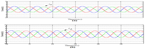
The
simulation of the inverters namely conventional three and two level inverter
was carried using sinusoidal pulse width modulation (SPWM) .it has shown that
decrease in voltage and current THD in moving from two level inverter to three level
inverter. This paper briefly explains theory of sinusoidal pulse width
modulation (SPWM) for two and three level inverter and performance of both
inverters was tested using RL load. It has shown that load current for three
level inverter are much more sinusoidal and improvement in the line current waveform
and decrease in the THD from two level to three level inverter and decrease in
the THD as the frequency is increased.
REFERENCES:
[1]
J. S. Lai and F.Z. Peng “Multilevel Converters – A new breed of power converters”
IEEE Trans. Ind Applicant , Vol. 32, May/June 1996.
[2]
Jose Roderiguez, Jih-Sheng Lai and Fang Zheng Reng, “Multilevel Inverters” A
survey of topologies ,control, and applications “,IEEE Trans. On
Ind.Electronics, vol No.[4], August 2002.
[3]
A. Nabae, I Takashashi, and H. Akagi, “ A new neutral –point clamped PWM
inverter,” IEEE Trans. Ind Application Vol. No. IA-17,PP 518-523,Sept/oc 1981.
[4]
P.K.Chaturvedi, S. Jain, Pramod Agrawal “ Modeling , Simulation and Analysis of
Three level Neutral Point CLAMPED inverter using matlab/Simulink/Power
System Blockst”
[5]
Bor-Ren Lin & Hsin – Hung Lu “ A Novel Multilevel PWM Control Scheme of the
AC/DC/AC converter for AC Drives”IEEE Trans on ISIE, 1999.