Grid Interactive PV System
with Harmonic and Reactive Power Compensation Features using a Novel Fuzzy
Logic Based MPPT
ABSTRACT:
Photovoltaic (PV) cell characteristics are highly nonlinear
that gives single Maximum Power Point (MPP) on P-V curve under uniform
insolation condition. The characteristics and hence MPP point changes with the
variation in insolation and temperature. In order to extract a maximum power
from PV array, a fuzzy based MPP tracking algorithm is proposed. The algorithm
accepts single input that is slope of P-V curve and generates the duty ratio as
an output that operates the boost converter to track MPP. The algorithm gives
faster convergence by applying variable step in duty ratio and gives accurate
MPP. The two stage grid interactive PV system described in this paper supplies
active power as well as provides harmonic and reactive power compensation. This
additional feature increases the effective utilization of PV inverter and
increases the overall efficiency of the system. The simulation results validate
the performance and stability of the grid interactive PV system using the
proposed algorithm for active current injection as well as harmonics and
reactive power compensation.
KEYWORDS:
1. Photovoltaic system
2. Maximum power point
tracking
3. Fuzzy logic controller
4. Harmonic elimination
SOFTWARE: MATLAB/SIMULINK
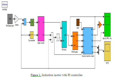
BLOCK DIAGRAM:

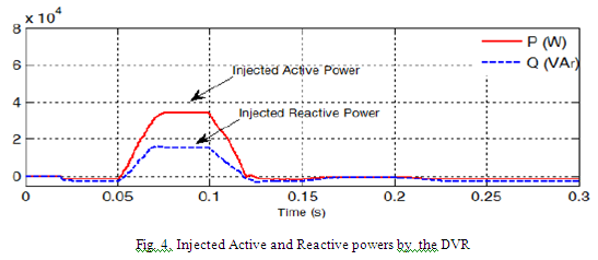
EXPECTED SIMULATION RESULTS:


CONCLUSION:
In
this paper, multi functional grid interactive PV system is presented using a
novel fuzzy logic based MPPT. The proposed MPPT controller is able to track the
MPP accurately under uniformly varying as well as rapidly changing insolation and
gives faster convergence as a variable step size in duty ratio is applied inherently
by the algorithm. The proposed fuzzy controller maintains the dc link voltage
within the limit for injecting the power into the grid. Apart from injecting active
power during day time, the PV inverter also compensates the harmonics and
reactive power during day time as well as at night. The current drawn from the
grid is sinusoidal and the total harmonic distortion is well below the specified
limit in the IEEE-519 standard. The simulation results validate the performance
of grid interactive PV system for both active power injection as well as shunt
active power filter functionality to mitigate the power quality issues thus increases
the utilization factor of the system.
REFERENCES:
[1] T. Esram and P. Chapman, “Comparision of
photovoltaic array maximum power point tracking techniques”, IEEE Trans. on
Energy Conversion, vol. 22, No. 2, June 2007.
[2]
S. Jain and V. Agarwal , “Comparison of the performance of maximum power point
tracking schemes applied to single-stage grid-connected photovoltaic systems”, IET
Electr. Power Appl., vol. 1, no. 756(5), pp. 753-762, September 2007.
[3]
P. Takun, S. Kaitwanidvilai and C. Jettanasen, “Maximum Power Point Tracking
using Fuzzy Logic Control for Photovoltaic Systems”, International
conference of engineers and computer scientists (IMECS), Vol.-II, pp.
986-990, March-2011.