ABSTRACT:
In this paper a high performance induction motor
drive without speed sensor is investigated. The rotor flux oriented indirect
vector control scheme is used for obtaining high performance. In order to
eliminate the speed sensor, a MRAS based speed estimator is designed for
gathering the rotor speed information. Also a simple but effective loss
minimization algorithm is integrated to calculate the optimal flux for
efficiency improvement of the drive. Complete simulation model is
developed in Simulink/MATLAB software. The
performance of the developed system I analyzed with different operating
conditions.
KEYWORDS:
1.Field oriented control,
2.induction motor,
3.sensorless,
4.loss minimization algorithm
SOFTWARE: MATLAB/SIMULINK
BLOCK DIAGRAM:
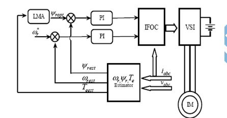

Fig.
2. Block diagram of rotor flux based MRAS speed estimator
EXPECTED SIMULATION RESULTS:

Fig. 3. Speed,
speed error and flux response with constant (rated) flux

Fig. 4. Speed, speed error
and flux response with optimal flux 
Fig. 5. Low speed tracking response of the drive with constant (rated) flux

Fig. 6. Low speed tracking response of the drive with optimal flux

Fig. 7. Drive response with step load
torque with constant flux mode

Fig.
8. Drive response with step load torque with optimal flux mode
CONCLUSION:
In this paper, developed model of sensor less
induction motor drive in Simulink/MATLAB software is investigated. Speed estimator
is also developed using rotor flux based MRAS technique for sensor less
operation. For efficiency improvement particularly under partial loads a model
based loss minimization technique is applied. The drive performance is
investigated for constant flux and the optimal flux. Drive shows good
performance with the optimal flux under various operating conditions
REFERENCES:
[1] E. Poirier, M. Ghribi and A. Kaddouri,
“Loss Minimization Control of Induction Motor Drives Based on Genetic
Algorithms”, IEEE Int. Conf. on Electric Machines and Drives, pp. 475–478,
2001.
[2] B. Kumar, ; Y. K Chauhan and V.
Shrivastava, “Performance analysis of induction motor drive with optimal rotor
flux for energy efficient operation”, IEEE Int. Conf. on Advanced Communication
Control and Computing Technologies (ICACCCT), pp. 319 – 322, 2014.
[3] A.V. Ravi Teja,; C. Chakraborty; S.
Maiti and Y. Hori, “A New Model Reference Adaptive Controller for Four Quadrant
Vector Controlled Induction Motor Drives”, IEEE Transactions on Industrial
Electronics, Vol. 59 , No. 10, pp. 3757 –
[4] B. Kumar, ; Y. K Chauhan and V.
Shrivastava, “Assessment of a fuzzy logic based MRAS observer used in a
Photovoltaic array supplied AC drive”, Frontiers in Energy, Vol. 8, No.1, pp.
81-89, 2014.
[5] S.M. Gadoue; D. Giaouris and J.W.Finch,
“MRAS Sensor less Vector Control of an Induction Motor Using New Sliding-Mode
and Fuzzy- Logic Adaptation Mechanisms”, IEEE Transactions on Energy Conversion,
Vol. 25 , No. 2, pp. 394 – 402, 2010. 3767, 2012.


