ABSTRACT:
With ever increasing oil prices and concerns for the
natural environment, there is a fast growing interest in electric vehicles
(EVs). However, energy storage is the weak point of the EVs that delays their
progress. For this reason, a need arises to build more efficient, light weight,
and compact electric propulsion systems, so as to maximize driving range per
charge. There are basically two ways to achieve high power density and high
efficiency drives. The first technique is to employ high-speed motors, so that
motor volume and weight are greatly reduced for the same rated output power. Most
adjustable speed drive systems employ a single three-phase induction motor.
With such a drive system, the drive has to be shut down if any phase fails. In
order to improve reliability of drive systems, six-phase induction motors fed
by double current source inverters have been introduced. Such a drive requires
a specially wound multiphase motor but enables the motor to continue to operate
at failure of any single drive unit, although it does degrade motor
performance. Compared to induction motors, permanent magnet (PM) motors have
higher efficiency due to the elimination of magnetizing current and copper loss
in the rotor. It has become possible because of their superior performance in
terms of high efficiency, fast response, weight, precise and accurate control,
high reliability, maintenance free operation, brushless construction and
reduced size. This project presents a current blocking strategy of brushless DC
(BLDC) motor drive to prolong the capacity voltage of batteries per charge in
electric vehicle applications. The BLDC motor employs a fuzzy controller for
torque hysteresis control (THC) that can offer a robust control and quick
torque dynamic performance. The proposed concept is verified by using
Matlab/Simulink software and the corresponding results are presented.
KEYWORDS:
1. Components
2. Brushless DC
motor
3. Hall effect
4. Current
controller
5. Electric
vehicle (EV)
6. Hybrid
electric vehicle (HEV)
7. Torque
hysteresis controller (THC)
8. Fuzzy logic controller
SOFTWARE: MATLAB/SIMULINK
BLOCK DIAGRAM:

Fig 1. Structure of Optimal Current Control drive
for BLDC motor.
CONTROL BLOCK DIAGRAM:

Fig 2.proposed blocking strategy based on hysteresis
comparator.
EXPECTED SIMULATION RESULTS:

Fig
3. Motor currents are controlled such that follow their references which are
generated according to the hall effect signals (Time/div=0.5s/div).

Waveform of current and emf

Waveform of speed
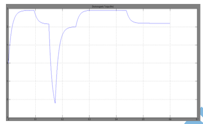
Waveform 0f torque
Fig
4 (a) THC without current blocking strategy

Waveform
of current and emf

Waveform of speed

Waveform of torque
Fig
5.(b) THC with current blocking strategy.
CONCLUSION:
This
project presented the modelling and experimental result of THC for BLDC motor.
The current controller has been applied to a BLDC drive and the results shows
that the current ripple stays within the hysteresis band as defined by the
controller. The proposed current blocking strategy shows that the energy
wastage from the batteries is prevented such that it can prolong the capacity
of voltage battery and it also showed that the hysteresis controller by using
fuzzy logic controller can offer inherent current protection/limitation and
robustness in controlling the motor torque.
REFERENCES:
[1] Lefley, P., L.
Petkovska, and G. Cvetkovski. Optimization of the design parameters of an
asymmetric brushless DC motor for cogging torque minimization in Power
Electronics and Applications (EPE 2011), Proceeding of the 2011-14th European
Conference on 2011.
[2] Bahari N.,
Jidin A., Abdullah A. R. and Othman M. N., “Modeling and Simulation of Torque
Hysteresis Controller for Brushless DC Motor Drives”, IEEE Symposium on
Industrial Electronics and Applications ISIEA, 2012.
[3] Mayer, J.S.
and O. Wasynczuk, “Analysis and modelling of a single-phase brushless DC motor
drive system”, Energy
[4] Jidin, A.,
Idris, N. R. N., Yatim, A. H. M., Sutikno, T. and Elbuluk, M. E. „An Optimized
Switching Strategy for Quick Dynamic Torque Control in DTC-Hysteresis-Based
Induction Machines‟, IEEE Transactions on Industrial Electronics,2011, Vol. 58,
pp. 3391-3400.
[5]
Norhazilina Binti Bahari; Jidin, Auzani bin; Abdullah, Abdul Rahim bin; Md
Nazri bin Othman; Manap, Mustafa bin, "Modeling and simulation of torque
hysteresis controller for brushless DC motor drives," Industrial
Electronics and Applications (ISIEA), 2012 IEEE Symposium on , vol., no.,
pp.152,155, 23-26 Sept. 2012


