asokatechnologies@gmail.com 09347143789/09949240245

Search This Blog

Wednesday 24 February 2016

High-Performance Multilevel Inverter Drive of Brushless DC Motor


ABSTRACT:

The brushless DC (BLDC) motor has numerous applications in high-power systems; it is simple in construction, is cheap, requires less maintenance, has higher efficiency, and has high power in the output unit. The BLDC motor is driven by an inverter. This paper presents design and simulation for a three-phase three-level inverter to drive the BLDC motor. The multilevel inverter is driven by discrete three-phase pulse width modulation (DPWM) generator that forced-commuted the IGBT’s three-level converters using three bridges to vectored outputs 12- pulses with three levels. Using DPWM with a three-level inverter solves the problem of harmonic distortions and low electromagnetic interference. This topology can attract attention in high-power and high-performance voltage applications. It provides a three-phase voltage source with amplitude, phase, and frequency that are controllable. The proposed model is used with the PID controller to follow the reference speed signal designed by variable steps. The system design is simulated by using Matlab/Simulink. Satisfactory results and high performance of the control with steady state and transient response are obtained. The results of the proposed model are compared with the variable DC-link control. The results of the proposed model are more stable and reliable.

KEYWORDS:

1.      Brushless DC Motor
2.       Multilevel Inverter
3.       High-Performance Drive
4.       Pulse Width Modulation (PWM)
5.      Maltlab
6.      Simulink

SOFTWARE: MATLAB/SIMULINK

BLOCK DIAGRAM:


                                                    Figure 1. Block diagram of a BLDC motor drive [18].

EXPECTED SIMULATION RESULTS:

                                       
Figure. 2. Output of three-phase three-level inverter with DPWM.
                                      
Figure 3. The sample from output of the DPWM
                                          
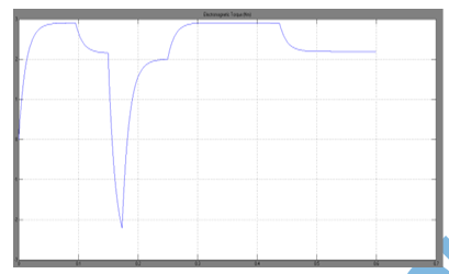
Figure 4. Analysis of response for the proposed MLI with PID controller of BLDC motor.

                                             
Figure 5. Two outputs of controllers with proposed MLI and variable DC-link

CONCLUSION:

The proposed MLI performance analysis was successfully presented by using Matlab/Simulink software. The proposed topology can be easily extended to a higher-level inverter. The simulation results were sine waves and exhibited fewer ripples and low losses. This system would show its feasibility in practice. The vector control was described in adequate detail and was implemented with a three-level MLI. This method enabled the operation of the drive at zero direct axis stator current. Transient results were obtained when a DPWM was started from a standstill to a required speed. The performance of the vector control in achieving a fast reversal of PDPWM even at very high speed ranges is quite satisfactory. The performance of the proposed three-phase MLI was investigated and was found to be quite satisfactory. A comparison was made between the PID controller–based proposed model MLI and the controller with variable DC-link voltage. The results showed that the proposed model responded better in transient and steady states and was more reliability with high performance.

REFERENCES:

[1] P. D. Kiran, M. Ramachandra, “Two-Level and Five-Level Inverter Fed BLDC Motor Drives”, International Journal of Electrical and Electronics Engineering Research, Vol. 3, Issue 3, pp 71-82, Aug 2013
[2] N. Karthika, A. Sangari, R. Umamaheswari , “Performance Analysis of Multi Level Inverter with DC Link Switches for Renewable Energy Resources”, International Journal of Innovative Technology and Exploring Engineering, Volume-2, Issue-6, pp 171-176, May 2013
[3] A. Jalilvand R. Noroozian M. Darabian, “Modeling and Control Of Multi-Level Inverter for Three-Phase Grid-Connected Photovoltaic Sources”, International Journal on Technical and Physical Problems of Engineering, Iss. 15, Vol. 5, No.2, pp 35-43, June 2013
[4] P. Karuppanan, K. Mahapatra, “PI, PID and Fuzzy Logic Controlled Cascaded Voltage Source Inverter Based Active Filter For Power Line Conditioners”, Wseas Transactions On Power Systems, Issue 4, Volume 6, pp 100-109, October 2011

[5] D. Balakrishnan, D. Shanmugam, K.Indiradevi, “Modified Multilevel Inverter Topology for Grid Connected PV Systems”, American Journal of Engineering Research, Vol. 02, Iss.10, pp-378-384, 2013

Tuesday 23 February 2016

A New Approach to Sensorless Control Method for Brushless DC Motors


 ABSTRACT:

This paper proposes a new position sensorless drive for brushless DC (BLDC) motors. Typical sensorless control methods such as the scheme with the back-EMF detection method show high performance only at a high speed range because the magnitude of the back-EMF is dependent upon the rotor speed. This paper presents a new solution that estimates the rotor position by using an unknown input observer over a full speed range. In the proposed method, a trapezoidal back-EMF is modelled as an unknown input and the proposed unknown input observer estimating a line-to-line back-EMF in real time makes it possible to detect the rotor position. In particular, this observer has high performance at a low speed range in that the information of a rotor position is calculated independently of the rotor speed without an additional circuit or complicated operation process. Simulations and experiments have been carried out for the verification of the proposed control scheme.

KEYWORDS:

1.      BLDC motor
2.      Full speed range
3.      Sensorless control
4.      Unknown input observer

SOFTWARE: MATLAB/SIMULINK

BLOCK DIAGRAM:


 Fig. 1. Overall structure of the proposed sensorless drive system.

EXPECTED SIMULATION RESULTS:
       
                       
(a)    Rotor speed.
                              
(b)   Load torque.
                              
(c)    Phase current.
                       
(d)   Line-to-line back-EMF.
                               
(e)    Commutation function.
                              
(f)    Commutation signal.
Fig. 2. Response waveforms at under step change of load torque. (Speed reference: 50 rpm, Load: 0.2 → 0.5 Nm).


(a)    Rotor speed.
                                     
(b)   Load torque.
                                 
(c)    Phase current.
                               
(d)   Line-to-line back-EMF.
                              
(e)    Commutation function.
                            
(f) Commutation signal.
Fig. 3. Response waveforms under step change of load torque. (Speed reference: 1650 rpm,
Load: 0.75 → 1.5 Nm).
                                     
(a)    Rotor speed.
                                
(b)   Speed reference.
                               
(c)    Phase current.
                              
(d)   Line-to-line back-EMF.
                         
(e)    Commutation function.
                          
(f) Commutation signal.
Fig. 4. Response waveforms under step change of speed reference. (Load: 0.75 Nm, Speed
reference: 50 → 1650 → 50 rpm).

CONCLUSION:

This paper presented a new approach to the sensorless control of the BLDC motor drives using the unknown input observer. This observer can be obtained effectively by using the equation of augmented system and an estimated line-to-line back- EMF that is modelled as an unknown input. As a result, the actual rotor position as well as the machine speed can be estimated strictly even in the transient state from the estimated line-to-line back-EMF. The novel sensorless method using an unknown input observer can
v   be achieved without additional circuits.
v   estimate a rotor speed in real time for precise control.
v   make a precise commutation pulse even in transient state as well as in steady state.
v   detect the rotor position effectively over a full speed range, especially at a low speed range.
v   calculate commutation function with a noise insensitive.
v   be easily realized for industry application by simple control algorithm.
The simulation and experimental results successfully confirmed the validity of the developed sensorless drive technique using the commutation function.

 REFERENCES:

[1] N. Matsui, “Sensorless PM brushless DC motor drives,” IEEE Trans. on Industrial Electronics, vol. 43, no. 2, pp. 300-308, 1996.
[2] K. Xin, Q. Zhan, and J. Luo, “A new simple sensorless control method for switched reluctance motor drives,” KIEE J. Electr. Eng. Technol., vol. 1, no. 1, pp. 52-57, 2006.
[3] S. Ogasawara and H. Akagi, “An approach to position sensorless drive for brushless DC motors,” IEEE Trans. on Industry Applications, vol. 27, no. 5, pp. 928-933, 1991.
[4] J. C. Moreira, “Indirect sensing for rotor flux position of permanent magnet AC motors operating over a wide speed range,” IEEE Trans. on Industry Applications, vol. 32, no. 6, pp. 1394-1401, 1996.

[5] J. X. Shen, Z. Q. Zhu, and D. Howe, “Sensorless flux-weakening control of permanent-magnet brushless machines using third harmonic back EMF,” IEEE Trans. on Industry Applications, vol. 40, no. 6, pp. 1629-1636, 2004.

Friday 19 February 2016

Torque Hysteresis Control of BLDC Drives for EV Application by using fuzzy logic controller


ABSTRACT:
With ever increasing oil prices and concerns for the natural environment, there is a fast growing interest in electric vehicles (EVs). However, energy storage is the weak point of the EVs that delays their progress. For this reason, a need arises to build more efficient, light weight, and compact electric propulsion systems, so as to maximize driving range per charge. There are basically two ways to achieve high power density and high efficiency drives. The first technique is to employ high-speed motors, so that motor volume and weight are greatly reduced for the same rated output power. Most adjustable speed drive systems employ a single three-phase induction motor. With such a drive system, the drive has to be shut down if any phase fails. In order to improve reliability of drive systems, six-phase induction motors fed by double current source inverters have been introduced. Such a drive requires a specially wound multiphase motor but enables the motor to continue to operate at failure of any single drive unit, although it does degrade motor performance. Compared to induction motors, permanent magnet (PM) motors have higher efficiency due to the elimination of magnetizing current and copper loss in the rotor. It has become possible because of their superior performance in terms of high efficiency, fast response, weight, precise and accurate control, high reliability, maintenance free operation, brushless construction and reduced size. This project presents a current blocking strategy of brushless DC (BLDC) motor drive to prolong the capacity voltage of batteries per charge in electric vehicle applications. The BLDC motor employs a fuzzy controller for torque hysteresis control (THC) that can offer a robust control and quick torque dynamic performance. The proposed concept is verified by using Matlab/Simulink software and the corresponding results are presented.

KEYWORDS:
1.      Components
2.       Brushless DC motor
3.       Hall effect
4.       Current controller
5.       Electric vehicle (EV)
6.       Hybrid electric vehicle (HEV)
7.       Torque hysteresis controller (THC)
8.      Fuzzy logic controller

SOFTWARE: MATLAB/SIMULINK

BLOCK DIAGRAM:
                            
         
Fig 1. Structure of Optimal Current Control drive for BLDC motor.

CONTROL BLOCK DIAGRAM:


Fig 2.proposed blocking strategy based on hysteresis comparator.

EXPECTED SIMULATION RESULTS:


Fig 3. Motor currents are controlled such that follow their references which are generated according to the hall effect signals (Time/div=0.5s/div).


Waveform of current and emf


Waveform of speed


Waveform 0f torque
Fig 4 (a) THC without current blocking strategy


Waveform of current and emf


Waveform of speed


Waveform of torque
Fig 5.(b) THC with current blocking strategy.

CONCLUSION:

This project presented the modelling and experimental result of THC for BLDC motor. The current controller has been applied to a BLDC drive and the results shows that the current ripple stays within the hysteresis band as defined by the controller. The proposed current blocking strategy shows that the energy wastage from the batteries is prevented such that it can prolong the capacity of voltage battery and it also showed that the hysteresis controller by using fuzzy logic controller can offer inherent current protection/limitation and robustness in controlling the motor torque.

REFERENCES:

[1] Lefley, P., L. Petkovska, and G. Cvetkovski. Optimization of the design parameters of an asymmetric brushless DC motor for cogging torque minimization in Power Electronics and Applications (EPE 2011), Proceeding of the 2011-14th European Conference on 2011.
[2] Bahari N., Jidin A., Abdullah A. R. and Othman M. N., “Modeling and Simulation of Torque Hysteresis Controller for Brushless DC Motor Drives”, IEEE Symposium on Industrial Electronics and Applications ISIEA, 2012.
[3] Mayer, J.S. and O. Wasynczuk, “Analysis and modelling of a single-phase brushless DC motor drive system”, Energy
[4] Jidin, A., Idris, N. R. N., Yatim, A. H. M., Sutikno, T. and Elbuluk, M. E. „An Optimized Switching Strategy for Quick Dynamic Torque Control in DTC-Hysteresis-Based Induction Machines‟, IEEE Transactions on Industrial Electronics,2011, Vol. 58, pp. 3391-3400.

[5] Norhazilina Binti Bahari; Jidin, Auzani bin; Abdullah, Abdul Rahim bin; Md Nazri bin Othman; Manap, Mustafa bin, "Modeling and simulation of torque hysteresis controller for brushless DC motor drives," Industrial Electronics and Applications (ISIEA), 2012 IEEE Symposium on , vol., no., pp.152,155, 23-26 Sept. 2012

Thursday 18 February 2016

Current Control of BLDC Drives for EV Application


ABSTRACT:

This paper presents a current blocking strategy of brushless DC (BLDC) motor drive to prolong the capacity voltage of batteries per charge in electric vehicle applications. The BLDC motor employs a simple torque hysteresis control (THC) that can offer a robust control and quick torque dynamic performance. At first, a mathematical modeling of BLDC motor and principle of torque hysteresis control will be described, so that the benefit offered by the proposed current blocking strategy can be highlighted. It can be shown that the current control method naturally provides current limitation, in which the current error (or ripple) is restricted within the pre-defined band-gap furthermore provide current protection. The benefit of proposed current blocking strategy will be highlighted such that it can prevent the current drained from the batteries when the torque demand is released to set to 0 Nm. The control scheme is validated and verified by the simulation and experimental results.

KEYWORDS:
1.      Components
2.      Brushless DC motor
3.      Hall effect
4.      Current controller
5.      Electric vehicle (EV)
6.      Hybrid electric vehicle (HEV)
7.      Torque hysteresis controller (THC)

SOFTWARE: MATLAB/SIMULINK

BLOCK DIAGRAM:

 
Fig 1. Structure of Optimal Current Control drive for BLDC motor.


 CONTROL BLOCK DIAGRAM:

               
Fig 2. Proposed current blocking strategy based on hysteresis comparator


 EXPECTED SIMULATION RESULTS:


Fig 3. Motor currents are controlled such that follow their references which are generated according to the hall effect signals (Time/div=0.5s/div).
                
                        
Fig 4. Waveforms of output torque, speed and currents (a) THC without current blocking strategy (b) THC with current blocking strategy.

CONCLUSION:

This paper presented the modelling and experimental result of THC for BLDC motor. The current controller has been applied to a BLDC drive and the results shows that the current ripple stays within the hysteresis band as defined by the controller. The proposed current blocking strategy shows that the energy wastage from the batteries is prevented such that it can prolong the capacity of voltage battery and it also showed that the hysteresis controller can offer inherent current protection/limitation and robustness in controlling the motor torque.

REFERENCES:

[1] Lefley, P., L. Petkovska, and G. Cvetkovski. Optimization of the design parameters of an asymmetric brushless DC motor for cogging torque minimization in Power Electronics and Applications (EPE 2011), Proceeding of the 2011-14th European Conference on 2011.

[2] Bahari N., Jidin A., Abdullah A. R. and Othman M. N., “Modeling and Simulation of Torque Hysteresis Controller for Brushless DC Motor Drives”, IEEE Symposium on Industrial Electronics and Applications ISIEA, 2012.

[3] Mayer, J.S. and O. Wasynczuk, “Analysis and modelling of a single-phase brushless DC motor drive system”, Energy Conversion, IEEE Transactions on, 1989. 4(3): p. 473-479.

[4] Jidin, A., Idris, N. R. N., Yatim, A. H. M., Sutikno, T. and Elbuluk, M. E. ‘An Optimized Switching Strategy for Quick Dynamic Torque Control in DTC-Hysteresis-Based Induction Machines’, IEEE Transactions on Industrial Electronics,2011, Vol. 58, pp. 3391-3400.

[5] Norhazilina Binti Bahari; Jidin, Auzani bin; Abdullah, Abdul Rahim bin; Md Nazri bin Othman; Manap, Mustafa bin, "Modeling and simulation of torque hysteresis controller for brushless DC motor drives," Industrial Electronics and Applications (ISIEA), 2012 IEEE Symposium on , vol., no., pp.152,155, 23-26 Sept. 2012