asokatechnologies@gmail.com 09347143789/09949240245

Search This Blog

Sunday 30 October 2016

Modeling and Simulation of a Stand-alone Photovoltaic System


ABSTRACT:
In the future solar energy will be very important energy source. More than 45% of necessary energy in the world will be generated by photovoltaic module. Therefore it is necessary to concentrate our forces in order to reduce the application costs and to increment their performances. In order to reach this last aspect, it is important to note that the output characteristic of a photovoltaic module is nonlinear and changes with solar radiation and temperature. Therefore a maximum power point tracking (MPPT) technique is needed to track the peak power in order to make full utilization of PV array output power under varying conditions. This paper presents two widely-adopted MPPT algorithms, perturbation & observation (P&O) and incremental conductance (IC). These algorithms are widely used in PV systems as a result of their easy implementation as well as their low cost. These techniques were analyzed and their performance was evaluated by using the Matlab tool Simulink.

KEYWORDS:
1.      Photovoltaic system
2.      MPPT
3.      Perturbation and Observation
4.      Incremental conductance


SOFTWARE: MATLAB/SIMULINK

 BLOCK DIAGRAM:


Fig. 1. Block diagram of the stand-alone PV system.
CIRCUIT DIAGRAM


Fig. 2. Model of the photovoltaic module


Fig. 3. Schematic diagram of a DC Buck-Boost converter.

EXPECTED SIMULATION RESULTS:


Fig. 4. Output current of PV module
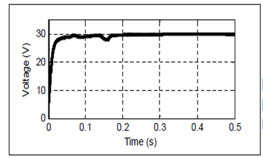
Fig. 5. Output voltage of PV module

Fig. 6 Output power of PV module

Fig. 7. Output current of MPPT+DC-DC converter


Fig. 8. Output voltage of MPPT+DC-DC converter

Fig. 9. Output power of MPPT+DC-DC converter

Fig 10 : PV-Output power with and without MPPT+DC-DC converter

Fig. 11. Output current of MPPT+DC-DC converter

Fig. 12. Output voltage of MPPT+DC-DC converter

Fig. 13. Output power of MPPT+DC-DC converter

Fig. 14. PV-Output power with and without MPPT+DC-DC converter
             
CONCLUSION:
In this work, we presented a modeling and simulation of a stand-alone PV system. One-diode model for simulation of PV module was selected; Buck-Boost converter is studied and applied to test the system efficiency. Two Maximum Power Point Tracking techniques, P&O and IC, are presented and analyzed. The proposed system was simulated using the mathematical equations of each component in Matlab/Simulink. The simulation analysis shows that P&O method is simple, but has considerable power loss because PV module can only run in oscillation way around the maximum power point. IC method has more precise control and faster response, but has correspondingly higher hardware requirement. In practice, in order to achieve maximum efficiency of photovoltaic power generation, a reasonable and economical control method should be chosen. The following of this work is based on optimizing the performance of PV modules and stand-alone systems using more efficient algorithms to minimize the influence of the meteorological parameters on the PV energy production.

REFERENCES:
[1] A.KH. Mozaffari Niapour, S. Danyali, M.B.B. Sharifian, M.R. Feyzi, “Brushless DC motor drives supplied by PV power system based on Zsource inverter and FL-IC MPPT controller”, Energy Conversion and Management 52, pp. 3043–3059, 2011.
[2] Reza Noroozian, Gevorg B. Gharehpetian, “An investigation on combined operation of active power filter with photovoltaic arrays”, International Journal of Electrical Power & Energy Systems, Vol. 46, Pages 392-399, March 2013.
[3] N. Femia, D. Granozio, G. Petrone, G. Spaguuolo, and M. Vitelli, “Optimized one-cycle control in photovoltaic grid connected applications”, IEEE Trans. Aerosp. Electron. Syst., Vol. 42, pp. 954- 972, 2006.
[4] T. L. Kottas, Y. S. Boutalis, and A. D. Karlis, “New maximum power point tracker for PV arrays using fuzzy controller in close cooperation with fuzzy cognitive net-work”, IEEE Trans. Energy Conv., Vol. 21, pp. 793–803, 2006.

[5] Mohamed A. Eltawil, Zhengming Zhao, “MPPT techniques for photovoltaic applications”, Renewable and Sustainable Energy Reviews, Vol. 25, P. 793-813, 2013.

Tuesday 27 September 2016

Review and Comparison of Step-Up Transformerless Topologies for Photovoltaic AC-Module Application


ABSTRACT:
This paper presents a comprehensive review of step-up single phase non isolated inverters suitable for ac-module applications. In order to compare the most feasible solutions of the reviewed topologies, a benchmark is set. This benchmark is based on a typical ac-module application considering the requirements for the solar panels and the grid. The selected solutions are designed and simulated complying with the benchmark obtaining passive and semiconductor components ratings in order to perform a comparison in terms of size and cost. A discussion of the analyzed topologies regarding the obtained ratings as well as ground currents is presented. Recommendations for topological solutions complying with the application benchmark are provided.

KEYWORDS:
1.      AC-module
2.      Photovoltaic(PV)
3.      Step-up Inverter
4.      Transformerless

SOFTWARE: MATLAB/SIMULINK

 BLOCK DIAGRAM:

Fig.1 Block diagram of a two stage topology for an ac module
STEP-UP TRANSFORMERLESS INVERTERS:

Fig 2 Boost converter and full bridge inverter

Fig 3 Time sharing boost converter with full bridge inverter

Fig 4 Parallel resonant soft switched boost converter and full bridge inverter

Fig 5 Parallel input series-output bipolar dc output converter and full bridge inverter

Fig 6 Boost converter and half bridge inverter

Fig 7 Boost converter and neutral point clamped inverter

Fig 8 Series combined boost and buck boost and half bridge inverter

Fig  9 Center-tapped coupled inductor converter with bipolar output and half bridge inverter


Fig 10 Single inductor bipolar output buck-boost converter and half bridge inverter

Fig  11 Boost + FB integrated and dual grounded

Fig 12 Block diagram of a pseudo-dc-link topology for an ac module

Fig 13 Buck-boost DCM converter and unfolding stage

Fig 14 Noninverting buck-boost DCM converter and unfolding stage

Fig 15 Switched inductor buck boost DCM converter and unfolding stage


Fig 16 Boost buck time sharing converter and unfolding stage

Fig 17 Block diagram of a single stage topology for an ac module

Fig 18 Universal single stage grid connected inverter

Fig 19 Integrated boost converter

Fig 20 Differential boost converter

Fig 21 Boost inverter with improved zero crossing.

Fig 22 Integrated Buck boost inverter

Fig 23 Buck Boost inverter with extended input voltage range

Fig 24 Differential buck boost inverter

Fig 25 Two sourced anti parallel buck boost inverter

Fig 26 Single stage full bridge buck boost inverter

Fig 27 Buck boost based single stage inverter

Fig 28 Switched inductor buck boost based single stage inverter
Fig 29 Single inductor buck boost based inverter

Fig 30 Doubly grounded single inductor buck boost based inverter

Fig 31 Single inductor  buck boost based inverter with dual ground

Fig 32 Three switch buck boost inverter

Fig 33 Coupled inductor buck boost inverter

Fig 34 Impedance-admittance conversion theory based inverter

Fig 35 Single phase Z source inverter
Fig 36 Semi quasi Z source inverter with continuous voltage gain

CONCLUSION:
In this paper, a comprehensive review of single phase non isolated inverters for ac module applications is presented. Both the grid connection and the solar panel requirements are analyzed emphasizing the leakage current regulation as it is a main concern in non isolated PV grid connected inverters. In order to compare the most suitable solutions of the reviewed topologies under the same specifications, a benchmark of a typical ac module application is set. These solutions have been designed and simulated, obtaining ratings for the passive and the semiconductor components. These ratings are used for the topology comparison in terms of size and cost. Furthermore, detailed simulations of representative topologies have been performed using semiconductor and inductor models to estimate the efficiency of the reviewed solutions. As a result of the comparison, the required voltage boost necessary for the connection to the European grid is difficult to achieve with transformerless topologies, but it is adequate for U.S. requirements. Two stage topologies, including the solution with dual grounding capability that theoretically avoids the ground leakage currents, are the preferred option for the set benchmark in which switching frequency for the dc-dc stage is set twice than for the dc-ac one. The two stage combination of a step-up dc-dc converter and a step-up inverter should be considered. In addition, the analyzed pseudo-dc-link approaches are an alternative solution in terms of size and cost. Furthermore, ground currents are expected to be low in these solutions because of the line frequency interface and weighted efficiency is the highest due to the flat behavior of the efficiency with the output power. The analyzed single stage topologies have higher cost than the other analyzed solutions and control is expected to be more complex to avoid dc current injection. In addition, DCM operation mode allows smaller solutions, including a solution with dual ground capability, but efficiency is lower due to the high RMS currents.