ABSTRACT
The
dynamic voltage restorer (DVR) is one of the modern devices used in
distribution systems to protect consumers against sudden changes in voltage
amplitude. In this paper, emergency control in distribution systems is analysed
by using the proposed multi functional DVR control strategy. Also, the multi loop
controller using the Posicast and P+Resonant controllers is proposed in order
to improve the transient response and eliminate the steady-state error in DVR
response, respectively. The proposed algorithm is applied to some disturbances
in load voltage caused by induction motors starting, and a three-phase short
circuit fault. Also, the capability of the proposed DVR has been tested to
limit the downstream fault current. The current limitation will restore the
point of common coupling (PCC) (
(the bus to which all feeders under study are connected) voltage and protect
the DVR itself. The idea here is that the DVR acts as a virtual impedance with
the main aim of protecting the pee voltage during downstream fault without any
problem in real power injection into the DVR. Simulation results obtained using
MATLAB software show the capability of the DVR to control the emergency
conditions of the distribution systems.
KEYWORDS:
1. DVR
2. Power
System
3. PCC
4. Resonant
controllers
5. Closed
loop control.
SOFTWARE: MATLAB/SIMULINK
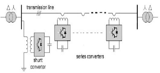
BLOCK DIAGRAM:

Fig.1.
Representation of DVR system Injection/booster transformer
EXPECTED SIMULATION RESULTS:

Fig.2. Simulation showing the sag
in the closed loop system

Fig.3. Simulation showing the swell
in closed loop system

Fig .4. Simulation showing the
output after DVR is connected

Fig.5. Output for real and reactive
power control

Fig.6. Waveform for the fault
analysis

Fig.7. output of FFT analysis for
input!
CONCLUSION
The
main purpose of using DVR in industries is to maximize efficiency in
production. We choose the proposed an improved progressive phase changing
scheme of post fault voltage. For any fault situation of voltage sag this method
is effective which is proved from the analysis and
MATLAB
simulation results. We chose MATLAB programming because it is easy and can be
easily fed in any microprocessor chip. The sag transients can be easily mitigated
and pre fault voltage can be established. For real time applications, this may
necessitate the application of the microcontroller/processor with fast speed.
The analysis done in this paper is detection and compensation of the voltage
sag with DVR active power injection.
REFERENCES
[1] J.
A. Martinez and J. M. Arnedo, "Voltage sag studies in distribution
networks- part T: System modeling," iEEE Trans. Power Del., vol. 21, no.
3, pp. 338-345, Jul. 2012.
[2] S. S. Choi, B. H. Li, and D. M. Vilathgamuwa,
"Dynamic voltage restoration with minimum energy injection," iEEE
Trans. Power Syst., vol. 15, no. I, pp. 51-57, Feb. 2011.
[3] C. Benachaiba and B. Ferdi, "Voltage
quality improvement using DVR," Electt. Power Qual. Utilisation, Journal,
vol. XIV, no. 1, 2010.
[4] D.
M. Vilathgamuwa, H. M. Wijekoon, and S. S. Choi, "A novel technique to
compensate voltage sags in multiline distribution systemthe interline dynamic
voltage restorer," iEEE Trans. ind. Electron., vol. 53, no. 5, pp.
1603-1611, Oct. 2012.
[5] M.
I. Marei, E. F. EI-Saadany, and M. M. A. Salama, "A new approach to
control DVR based on symmetrical components estimation," iEEE Trans. Power
Del., vol. 22, no. 4, pp. 2017-2024, Oct. 2012.