asokatechnologies@gmail.com 09347143789/09949240245

Search This Blog

Thursday 29 June 2017

A High-Switching-Frequency Flyback Converter in Resonant Mode

ABSTRACT
The demand of miniaturization of power systems has accelerated the research on high-switching-frequency power converters. A flyback converter in resonant mode that features low switching losses, less transformer losses, and low switching noise at high switching frequency is investigated in this paper as alternative to a conventional quasi-resonant flyback topology to increase power density. In order to find a compromise between magnet size, electromagnetic interference (EMI), and efficiency, the concept utilizes the resonant behavior between transformer leakage inductance and snubber capacitor to achieve near-zero-voltage switching at both turn-on and turn-off of the primary switch, low core loss due to a continuous transformer magnetizing current, and reduced EMI due to low di/dt and dv/dt values. Meanwhile, the concept uses the regenerative snubber to recycle the transformer leakage energy with two snubber diodes and one snubber capacitor. The proposed concept has been validated on a 340kHz 65W prototype. Compared to the conventional quasi-resonant flyback converter operating at the same switching frequency, the proposed concept has 2% efficiency improvement and better EMI performance.

KEYWORDS:

1.        Resonant power conversion
2.       High switching frequency
3.       Flyback
4.       Switching loss
5.       Regenerative snubber.
SOFTWARE: MATLAB/SIMULINK

CIRCUIT DIAGRAM:

Fig. 1 Proposed flyback converter, (a) schematic of the proposed concept, (b) equivalent circuit of the proposed concept.
  

EXPECTED SIMULATION RESULTS:


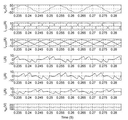
Fig. 2. Measured waveforms of resonant-mode operation, D = 0.6. (a) Switch Si voltage and current; (b) Current of each transformer winding (c) Snubber diode current, resonant capacitor voltage and current.

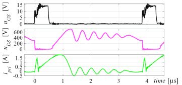
Fig.3. Measured waveforms of resonant flyback at high input voltage, Ui=360V, fs=250kHz, Po=38W.

CONCLUSION
In this paper, a flyback converter in resonant mode is proposed to enable soft switching, less transformer loss and reduced EMI at high switching frequency. Experimental results show that, compared to the conventional flyback converter operating in QR/DCM and while achieving the same specifications, both the fundamental quasi-peak and the high-frequency harmonics in the measured common-mode EMI are reduced due to the resonant behavior, and the switching loss on the primary switch is minimized due to the achieved soft switching in both turn-on and turn-off of the primary switch. Furthermore, the transformer core volume is reduced by one third compared to the low-frequency conventional flyback converter. In conclusion, the resonant-mode operation of the developed flyback converter enables higher power density, high efficiency and better EMI performance at high switching frequency. Therefore, the improved flyback topology is suitable for low-power isolated DC/DC converters with limited input voltage range.


REFERENCES
[1]   R. Watson; F.C. Lee; G.C. Hua, "Utilization of an active-clamp circuit to achieve soft switching in flyback converters," IEEE Transactions on Power Electronics, pp. 162 - 169, Jan 1996.
[2]   Y. Xi; P.K. Jain; G. Joos; Y. Liu, "An improved zero voltage switching flyback converter topology," in 29th Annual IEEE Power Electronics Specialists Conference, Fukuoka, May 1998.
[3]   Ching-Lung Chu; Ming-Juh Jong, "A zero-voltage-switching PWM flyback converter with an auxiliary resonant circuit," in International Conference on Power Electronics and Drive Systems, Taipei, Nov. 2009.
[4]   Y. Wei, X. Huang, J. Zhang and Z. Qian, "A Novel soft switching flyback converter with synchronous rectification," in IEEE 6th International Power Electronics and Motion Control Conference, Wuhan, May 2009.
[5]   "NCP4304: Secondary Side Controller," ON Semiconductor, 2015. [Online]. Available: http://www.onsemi.com/.


A PLL-Based Controller for Three-Phase Grid-Connected Power Converters

ABSTRACT
The current control of three-phase grid-connected converters is typically carried out by using a proportional resonant controller or synchronous reference frame proportional integral regulator. The implementation of these controllers often requires knowledge of the grid voltage frequency/phase angle, which is typically provided by a synchronization unit. It implies that dynamics and possible inaccuracies of the synchronization unit have a considerable impact on the current controller performance. The aim of this letter is to design an adaptive current controller by using a conventional synchronous reference frame phase-locked loop (SRF-PLL). In this way, the current controller and synchronization part are merged into a single unit, which results in a simpler and more compact structure. The effectiveness of the proposed controller is verified using experimental results.

KEYWORDS:
1.      Current control
2.      Distributed generation (DG) systems
3.      Phase-locked loop (PLL)
4.      Power converters
5.      Synchronization.

SOFTWARE: MATLAB/SIMULINK

CONTROL SYSTEM CIRCUIT DIAGRAM:

Fig. 1. Power stage of a three-phase VSC with the proposed PLL-based controller and a harmonic/imbalance compensator.

EXPECTED EXPERIMENTAL RESULTS:

Fig. 2. Experimental results for the test 1.

Fig. 3. Experimental results for the test 2.

Fig. 4. Experimental results for the test 3.

CONCLUSION
In this letter, a PLL-based controller for grid-connected converters was proposed. This controller, which is realized by adding a positive feedback loop to the conventional SRFPLL, eliminates the need for a dedicated synchronization unit and, therefore, results in a more compact structure. To enhance the harmonic/imbalance rejection capability of the suggested controller, multiple complex integrators tuned at low-order disturbance frequencies is employed. To simplify the tuning procedure, a simple yet accurate linear model describing the frequency estimation dynamics of the proposed controller was was verified using some experimental results. The main contribution of this letter is not the proposed controller. It is actually demonstrating the possibility of making a frequency-adaptive controller from a standard PLL. The importance of this contribution will be more evident when we notice that there are a large number of advanced PLLs which can be explored for the controller design.
REFERENCES
[1]   J. M. Carrasco, L. G. Franquelo, J. T. Bialasiewicz, E. Galvan, R. C. P. Guisado, M. A. M. Prats, J. I. Leon, and N. Moreno-Alfonso, “Powerelectronic systems for the grid integration of renewable energy sources: A survey,” IEEE Trans. Ind. Electron., vol. 53, no. 4, pp. 1002–1016, Jun. 2006.
[2]   F. Blaabjerg, Z. Chen, and S. B. Kjaer, “Power electronics as efficient interface in dispersed power generation systems,” IEEE Trans. Power Electron., vol. 19, no. 5, pp. 1184–1194, Sep. 2004.
[3]   B. K. Bose, “Power electronics and motor drives recent-progress and perspective,” IEEE Trans. Ind. Electron., vol. 56, no. 2, pp. 581–588, Feb. 2009.
[4]   F. Blaabjerg, R. Teodorescu, M. Liserre, and A. V. Timbus, “Overview of control and grid synchronization for distributed power generation systems,” IEEE Trans. Ind. Electron., vol. 53, no. 5, pp. 1398–1409, Oct. 2006.

[5]    Q. Zeng and L. Chang, “An advanced SVPWM-based predictive current controller for three-phase inverters in distributed generation systems,” IEEE Trans. Ind. Electron., vol. 55, no. 3, pp. 1235–1246, Mar. 2008.

Tuesday 27 June 2017

Experimental Design of a Nonlinear Control Technique for Three-Phase Shunt Active Power Filter

ABSTRACT
This paper presents a nonlinear control technique for a three-phase shunt active power filter (SAPF). The method provides compensation for reactive, unbalanced, and harmonic load current components. A proportional–integral (PI) control law is derived through linearization of the inherently nonlinear SAPF system model, so that the tasks of current control dynamics and dc capacitor voltage dynamics become decoupled. This decoupling allows us to control the SAPF output currents and the dc bus voltage independently of each other, thereby providing either one of these decoupled subsystems a dynamic response that significantly slower than that of the other. To overcome the drawbacks of the conventional method, a computational control delay compensation method, which delaylessly and accurately generates the SAPF reference currents, is proposed. The first step is to extract the SAPF reference currents from the sensed nonlinear load currents by applying the synchronous reference frame method, where a three-phase diode bridge rectifier with RL load is taken as the nonlinear load, and then, the reference currents are modified, so that the delay will be compensated. The converter, which is controlled by the described control strategy, guarantees balanced overall supply currents, unity displacement power factor, and reduced harmonic load currents in the common coupling point. Various simulation and experimental results demonstrate the high performance of the nonlinear controller.

KEYWORDS:
1.      Active power filter
2.      Control delay compensation,
3.      Modeling
4.      Nonactive load current compensation
5.      Nonlinearc control
6.      Power quality.

SOFTWARE: MATLAB/SIMULINK

BLOCK DIAGRAM:

Fig. 1. Basic circuit of SAPF.


EXPECTED SIMULATION RESULTS:

Fig. 2. Steady-state response of the SAPF.

Fig. 3. Spectrum of phase 1. (a) Load current. (b) Source current after
compensation.

Fig. 4. Dynamic response of SAPF under varying distorted nonlinear load
conditions.

Fig. 5. Steady-state response of SAPF with nonlinear load unbalances.

Fig. 6. Spectrum of load currents and source currents after compensation for
asymmetrical load conditions.


CONCLUSION
The nonlinear control algorithm of an SAPF has been implemented to enhance its response for compensation of nonactive load currents. The nonlinear control technique of the SAPF has been designed, which is based on two inner current loops and an outer dc bus voltage regulator loop. It addition to good performance in both steady-state and transient operations. Simulation and experimental results have validated the nonlinear control approach of the SAPF. It has been shown that the system has 1.5 cycles for the outer voltage loop and 0.5 cycles for the inner current loop and is able to keep the THD of the supply current below the limits specified by the IEEE- 519 standard. The obtained results have demonstrated the high performance of the SAPF.

REFERENCES
[1]   S. Senini and P. J. Wolfs, “Hybrid active filter for harmonically unbalanced three phase three wire railway traction loads,” IEEE Trans. Power Electron., vol. 15, no. 4, pp. 702–710, Jul. 2000.
[2]   S. Rahmani, K. Al-Haddad, H. Y. Kanaan, and B. Singh, “Implementation and simulation of a modified PWM with two current control techniques applied to a single-phase shunt hybrid power filter,” Proc. Inst. Elect. Eng.—Electr. Power Appl., vol. 153, no. 3, pp. 317–326, May 2006.
[3]   B. Singh, V. Verma, and J. Solanki, “Neural network-based selective compensation of current quality problems in distribution system,” IEEE Trans. Ind. Electron., vol. 54, no. 1, pp. 53–60, Feb. 2007.
[4]   B. R. Lin and C. H. Huang, “Implementation of a three-phase capacitor clamped active power filter under unbalanced condition,” IEEE Trans. Ind. Electron., vol. 53, no. 5, pp. 1621–1630, Oct. 2006.
[5]   R. Grino, R. Cardoner, R. Costa-Castello, and E. Fossas, “Digital repetitive control of a three-phase four-wire shunt active filter,” IEEE Trans. Ind. Electron., vol. 54, no. 3, pp. 1495–1503, Jun. 2007.

.

An Improved Control Scheme for Grid Connected Voltage Source Inverter

ABSTRACT
In grid connected Distribution Generation systems, Voltage Source Inverters are used for interfacing the renewable energy source to the utility grid. DG has variety of problems during grid integration. The power quality problems may cause problems to the industries ranging from malfunctioning of equipment to complete plant shut down. Disturbances from the utility grid including voltage sags, harmonics and the grid impedance will affect the grid connected voltage source inverters connected to the grid. Hence the control of the grid connected inverter plays an important role in feeding a grid with high quality power. This report presents an analysis of the stability problem of a grid connected with Voltage Source Inverter and with a LC filter. The possible grid-impedance variations have a significant influence on the system stability. Whenever the grid inductive impedance increases, the low frequency gain and the bandwidth of the Proportional Integral (PI) controller have to be decreased to maintain the system stable, thereby degrading the tracking performance and disturbance rejection capability. To overcome this problem an H∞ controller is proposed with an explicit robustness in terms of grid impedance variations to incorporate the desired tracking performance and stability margin. The proposed method is simulated by using MATLAB/SIMULINK. The results of the proposed H∞ controller and the conventional PI controller are compared, which validates the performance of the proposed control scheme.

KEYWORDS:

1.      Distributed Generation (DG)
2.      Voltage Source Inverter (VSC)
3.      LC Filter
4.      H∞ Controller
5.      Total Harmonic Distortion (THD).

SOFTWARE: MATLAB/SIMULINK

SIMULINK BLOCK DIAGRAM:


Figure.1.Overall Simulink Model


EXPECTED SIMULATION RESULTS:


Figure.2.Waveform for output voltage of PV module


Figure.3.Output current waveform of overall system


Figure.4.THD analysis with Lg=0.3 mH and rg= 0.2Ω


Figure.5.THD analysis with Lg=0.15 mH and rg=0.2Ω


CONCLUSION
In the grid connected VSI with LC filters, the possible wide range of grid impedance variations can challenge the design of the controller, particularly when the grid impedance is highly inductive. In this project, the suitability of an H∞ controller to get the desired tracking performance and stability margin is investigated. From the software results it is seen that the grid current THD of the H∞ controller are always lower than that of the PI controller, which satisfy the THD requirement of IEEE Std.1547-2003 (i.e.,5%). Further simulation work is based on demonstrating the operation of a grid in Grid connected mode and intentional islanded mode. Through this, the system is able to determine whether or not it is safe to remain connected to the grid. An islanding detection algorithm is used to act as a switch between the two controllers and this minimizes the effect of losses in the time of transition, and also to prevent the undesirable feeding of loads during fault conditions.

REFERENCES
[1]   .Asiminoaei, L., Teodorescu,R.,Blaabjerg,F., and Borup, U., “A New Method Of On-Line Grid Impedance Estimation for PV Inverter,” in Proc. IEEE APEC, San Diego, CA, Feb. 2004, pp. 1527–1533.
[2]    Bierhoff, M. H., and Fuchs,F. W., “Active Damping for Three-Phase PWM Rectifiers with High-Order Line-Side Filters,” IEEE Trans. Ind. Electron., vol. 56, no. 2, pp. 371–379, Feb. 2009.
[3]    Bin Yu and Liuchen Chang, “Improved Predictive Current Controlled PWM for Single-Phase Grid-Connected Voltage Source Inverters,” in Proc. IEEE PESC, 2005, pp. 231 - 236.

[4]    Blaabjerg, F., Teodorescu, R., and Liserre, M., “Overview of Control and Grid Synchronization for Distributed Power Generation Systems,” IEEE Trans. Ind. Electron., vol. 53, no. 5, pp. 1398–1409, Oct. 2006. 

Variable and Fixed Switching Frequency Based HCC Methods for Grid-Connected VSI with Active Damping and Zero Steady State Error


ABSTRACT

This paper presents variable and fixed switching frequency based hysteresis current control (HCC) methods for single-phase grid-connected voltage source inverters (VSI) with LCL filter. The main feature of the proposed HCC methods is that the reference inverter current is generated through a proportional-resonant (PR) controller for achieving zero steady-state error in the grid current. The consequence of using PR controller is eliminating the need for using derivative operations in generating the reference inverter current. Furthermore, active damping method is employed to damp the LCL resonance. An equation is derived for variable switching frequency. Fixed switching frequency operation is achieved by modulating the hysteresis band. The performance of both HCC methods has been validated by simulation and experimentally. It is reported that the proposed HCC methods not only preserve the inherent features of the conventional HCC methods, but also damp the LCL resonance using an active damping method and guarantee zero steady-state error in the grid current.

KEYWORDS:

1.      Fixed switching frequency
2.      Grid-connected inverter
3.      Hysteresis current control
4.      Variable switching frequency.

SOFTWARE: MATLAB/SIMULINK

BLOCK DIAGRAM:


Fig. 1. Single-phase grid-connected VSI with the proposed HCC methods. (a) Variable switching frequency based HCC, (b) Fixed switching frequency based HCC.


EXPECTED SIMULATION RESULTS:


Fig. 2. Simulation and experimental results of , , , and obtained by: (a) the variable switching frequency based HCC, (b) the fixed switching frequency based HCC. 1 i * ,1damp i2 i2 *2 i i


Fig. 3. Simulation and experimental results of , , and obtained by: (a) the variable switching frequency based HCC, (b) the fixed switching frequency based HCC. 2 ig vsw f

CONCLUSION
In this study, variable and fixed switching frequency based HCC methods are presented for single-phase grid-connected VSI with LCL filter. Unlike the conventional HCC methods, the proposed HCC methods employ the reference inverter current generated with the PR current controller by processing the grid current error. The use of PR controller ensures zero steady-state error in the grid current independently from the hysteresis bandwidth. In addition, the need for using derivative operations in generating the reference inverter current is eliminated by using PR controller. Also, active damping method is employed to damp the LCL resonance. A formula is derived for the variable switching frequency. The fixed switching frequency operation is achieved by modulating the hysteresis band obtained from the derived variable switching frequency equation. The performances of both HCC methods are validated by experimental investigation. These results show excellent performance in terms of dynamic response, robustness, zero steady-state error, and low THD in the grid current. Hence, the proposed HCC methods not only preserve the inherent features of the HCC methods, but also damp the LCL resonance using an active damping method and guarantee zero steady-state error in the grid current.

REFERENCES
[1]   F. Blaabjerg, R. Teodorescu, M. Liserre, and A. V. Timbus, “Overview of control and grid synchronization for distributed power generation systems,” IEEE Trans. Ind. Electron., vol. 53, no. 5, pp. 1398–1409, Oct. 2006.
[2]   H. Abu-Rub, M. Malinowski, and K. Al-Haddad, Power Electronics for Renewable Energy Systems, Transportation and Industrial Applications. Hoboken, NJ, USA: Wiley, 2014.
[3]   R. Pena-Alzola, M. Liserre, F. Blaabjerg, R. Sebastion, J. Dannehl, and F. W. Fuchs, “Analysis of the passive damping losses in LCL-filter-based grid converters,” IEEE Trans. Power Electron., vol. 28, no. 6, pp. 2642–2646, Jun. 2013.
[4]   J. Dannehl, F. W. Fuchs, S. Hansen, and P. B. Thogersen,”Investigation of active damping approaches for PI-based current control of grid-connected pulse width modulation converters with LCL filters,” IEEE Trans. Ind. Appl., vol. 46, no. 4, pp. 1509-1517, Jul./Aug. 2010.

[5]   D. Pan, X. Ruan, C. Bao, W. Li, and X. Wang, “Capacitor-current feedback active damping with reduced computation delay for improving robustness of LCL-type grid-connected inverter,” IEEE Trans. Power Electron., vol. 29, no. 7, pp. 3414–3427, Jul. 2014.

Fixed-Frequency Generalized Peak Current Control (GPCC) for Inverters


ABSTRACT
A fast and robust fixed switching frequency peak current controller for dc-ac converters is presented. The method is specifically elaborated for single-phase grid-connected distributed generation (DG) applications. This method is called generalized peak current control (GPCC) as it can mimic any known pulse width modulation (PWM) strategy. It is shown that additional control objectives can be achieved by adaptive bands of the GPCC, which are proposed to provide active damping for inverters with LCL output filters. The proposed approach features all the advantages of peak current controllers such as simplicity, fast transient, and optimum dynamic response; with the superiority of fixed switching frequency and harmonic free output. Feasibility and performance of the controller is shown by simulations and experimental results.

KEYWORDS:
1.      Current Control
2.      DC-AC Converters
3.      Generalized Peak Current Control (GPCC)
4.      Switching Scheme
5.      Single-Phase Grid-Connected Inverter

SOFTWARE: MATLAB/SIMULINK
  
BLOCK DIAGRAM:

Fig. 1. Block diagram of the proposed controller along with the cost effective
active resonant damping technique.

EXPECTED SIMULATION RESULTS:

Fig. 2. (a) Grid current for the LCL filter case when the active damping
branch is disabled, (b) Current of inverter and grid with the proposed active damping.


Fig. 3. Dynamic performance evaluation of proposed GPCC. Peak current
reference jumps from 1A to 3A at t = 0:1s.

CONCLUSION
A fixed switching frequency Generalized Peak Current Control (GPCC) method for inverters is proposed . While controlling the peak value of the inverters’ current, the proposed approach can mimic any known PWM strategy. As a result, the GPCC features all the advantages of peak current controllers, along with a fixed switching frequency and the clean output harmonic spectrum inheriting from the original PWM scheme. It is shown that the proposed technique is able to obtain additional control objectives by its adaptive bands. As an example, the GPCC is applied to a unipolar PWM scheme and the controller is elaborated for both Land LCL-type output filters. Demonstrating the advantages of resulting controller, a simple active damping strategy based on adaptive bands of the controller is proposed. Simulations and experimental results are presented to validate the method.

REFERENCES
[1]   R. Gupta, “Generalized frequency domain formulation of the switching frequency for hysteresis current controlled vsi used for load compensation,” Power Electronics, IEEE Transactions on, vol. 27, no. 5, pp. 2526–2535, May 2012.
[2]   F. Blaabjerg, R. Teodorescu, M. Liserre, and A. Timbus, “Overview of control and grid synchronization for distributed power generation systems,” Industrial Electronics, IEEE Transactions on, vol. 53, no. 5, pp. 1398–1409, Oct 2006.
[3]   L. Malesani and P. Tenti, “A novel hysteresis control method for currentcontrolled voltage-source pwm inverters with constant modulation frequency,” Industry Applications, IEEE Transactions on, vol. 26, no. 1, pp. 88–92, 1990.
[4]   L. Malesani, L. Rossetto, and A. Zuccato, “Digital adaptive hysteresis current control with clocked commutations and wide operating range,” Industry Applications, IEEE Transactions on, vol. 32, no. 2, pp. 316– 325, 1996.

[5]   B. Bose, “An adaptive hysteresis-band current control technique of a voltage-fed pwm inverter for machine drive system,” Industrial Electronics, IEEE Transactions on, vol. 37, no. 5, pp. 402–408, Oct 1990.