asokatechnologies@gmail.com 09347143789/09949240245

Search This Blog

Wednesday 14 March 2018

Design and Implementation of Sliding Mode and PI Controllers based Control for Three Phase Shunt Active Power Filter


ABSTRACT:
This paper presents a simulation and experimental comparative study of Sliding Mode Controller (SMC) and Proportional Integral (PI) regulator based the control of the DC bus voltage of three phase shunt Active Power Filter (APF). The capacitor that feeds the active filter plays the role of a voltage source. This tension must be kept constant, so as not to degrade the filter performances, and not to exceed the voltage of semiconductors. The main cause of the variation of this voltage is the change in the pollutant load, which creates an active power exchange with the network (if the inverter provides power active, then the average voltage across the capacitor will decrease and if the inverter consumes power active, then the average voltage across the capacitor will increase). The algorithm used to identify the reference currents is based on the Self Tuning Filter (STF). This study was verified experimentally, using a hardware prototype based on dSPACE-1104.

KEYWORDS:
1.      Active Power Filter (APF)
2.       Sliding Mode Controller (SMC)
3.      Self Tuning Filter (STF)
4.       Proportional Integral (PI) Controller

SOFTWARE: MATLAB/SIMULINK

BLOCK DIAGRAM:


Fig. 1. Basic compensation principle of the shunt APF.

 EXPECTED SIMULATION RESULTS:


Fig.2. Simulation APF with PI: capacitor voltage Vdc (V); source current iS (A) and load current iL(A).


Fig.3. Simulation APF with SMC: capacitor voltage Vdc (V); source current iS (A) and load current iL(A).

CONCLUSION:
 Two different control strategies for a three-phase shunt active power filter employing a digital signal processor DSP were presented in this paper. The first is based on sliding mode control SMC and the second uses a single proportional-integral controller PI. These controllers are used in order to regulate the DC voltage of the three phase shunt active power filter and improving the dynamical performances. Several tests have been performed in order to prove the efficiency of the type of the control. The results obtained by simulations and Experimental, show that the SMC controller offers better performances than the PI.
REFERENCES:
[1] Das J.C (2004), “Passive filters- Potentialities and limitations”, IEEE-Transactions on industry applications; 40(1): 232– 241.
[2] Wei Zhao, An Luo, Ke Peng, Xia Deng “Current control for a shunt hybrid active power filter using recursive integral PI” Journal of Control Theory and Applications, February 2009, Volume 7, Issue 1, 77-80.
[3] Mekri F, Machmoum M, Mazari B and Ahmed N A.( 2007) “Determination of voltage references for series active pow er filter based on a robust PLL system”. In: IEEE International Symposium on Industrial Electronics. p.473 – 78.
[4] Karimi S. ,Poure P. ,Saadate S. , Gholipour E. (2008), ‘FPGA-based fully digital controller for three-phase shunt active filters’, International Journal of Electronics, 95( 8), 805–818.
[5] Abdusalam M, Poure P, Saadate S. (2008) “Study and experimental validation of harmonic isolation based on Self -Tuning-Filter for threephase active filter”, In: IEEE International Symposium on Industrial Electronics,166 – 71.

Control of the Shunt Active Power Filter under Non- Ideal Grid Voltage and Unbalanced Load Conditions


ABSTRACT:
In this study a new method is proposed in order to improve the harmonic suppression efficiency of Active Power Filter for the problems caused by the distorted and unbalanced voltages with unbalanced load currents in control strategy. The proposed control method gives an adequate compensating current reference even for non ideal voltage and unbalanced current conditions. The results of simulation study are presented to verify the effectiveness of the proposed control technique in this study.
KEYWORDS:
1.      Active Power Filter
2.      Park Transformation
3.      Clark Transformation
4.       Self Tuning Filter
5.      Unbalanced Load Currents and Voltages

SOFTWARE: MATLAB/SIMULINK

 BLOCK DIAGRAM:


Fig. 1. Block diagram of the APF

 EXPECTED SIMULATION RESULTS:


Fig. 2. Three phase unbalanced and distorted (non-ideal) grid voltage


Fig. 3. Unbalanced varying load current under non-ideal voltage condition.


Fig. 4. Voltage waveforms, a-) Three phase unbalanced and distorted grid voltages, b-) Grid voltages after transformation to α-β ( at the input of STF), c-) The obtained balanced and undistorted two phase voltage waveforms (at the output of STF), d-) The obtained balanced and undistorted three phase voltage waveforms (at the input of PLL).


Fig. 5. DC-link terminal voltage with the proposed control method


Fig. 6. Three phase converter currents

Fig. 7. Grid current after filtering by proposed control method under distorted and un-balanced grid voltage with unbalanced load conditions


CONCLUSION:

In this paper, we have considered to design a control method in order to generate correct reference current signal to satisfy the requirements of harmonic suppressing and reactive power compensation for the unbalanced nonlinear loads combination under case of non-ideal grid voltage conditions. In the propose method, the distorted and unbalanced voltages first processed by using Self Tuning Filter to determine the correct angular positions. Then second STF is used to extract balanced load current waveforms after obtaining the fundamental and harmonic components of instantaneous currents by using park transformation. In this study, additional low-pass or high-pass filter is not used to extract harmonic components from the fundamental. The simulation studies shows that the proposed control technique gives an adequate compensating current references.

REFERENCES 

[1] W. M. Grady, S. Santoso, "Understanding power system harmonics", IEEE Power Eng., Rev. 21, pp. 8-11.
[2] B. Singh, K. Al-Haddad, K, A. Chandra, "A review of active filters for power quality improvement", IEEE Transaction on Industrial Electronics., vol. 46, no. 5, pp. 960–971, 1999.
[3] N. Mariun, A. Alam, S. Mahmod, H. Hizam, "Review of control strategies for power quality conditioners", PECon 2004, Power and Energy Conference, vol., no., pp. 109- 115, 29-30 Nov. 2004.
[4] H. S. Song, “Control scheme for PWM converter and phase angle estimation algorithm under voltage unbalance and/or sag condition”, Ph.D. thesis in Electronic and Electrical Engineering. South Korea, 2000.
[5] M. Abdusalam, P. Poure, S. Saadate, “A New Control Scheme of Hybrid Active Filter Using Self-Tuning-Filter,” POWERENG 2007 International Conference on Power Engineering, Energy and Electrical Drives, 2007, vol., no., pp.35-40, 12-14 April 2007.


Monday 12 March 2018

The Benefit of Harmonics Current Using a New Topology of Hybrid Active Power Filter


ABSTRACT:

This paper presents a new idea to benefit of eliminated harmonics current by using a new topology of hybrid active power filter (HAPF) to compensate harmonics current to be sinusoidal in order to feed some loads. The design and simulation of a new three phase HAPF circuit using a shunt active power filter (APF) connected in parallel with a capacitor (C) line of a (LC) low pass filter (LPF) has been submitted.
The first aim of the new circuit is to use the LPF as a path to pass the fundamental frequency (50 Hz) current and eliminate other high order frequencies, while APF compensates high order frequencies and compensate reactive power of the circuit. The second aim is to benefit from the modified wave in the high frequency branch of LPF to use it as a useful power in order to feed different loads. In addition, With this topology, the resonance problem (which usually happens between LPF and the system) will disappear because of using of APF in the high frequency branch.
The control circuit has been designed based on the instantaneous reactive power theory. A Clarke transformation equations and hysteresis current controller have been used in the HAPF’s design. The proposed circuit has provided a good harmonic elimination, total harmonic distortion (THD) reduced, reactive power compensation and a reasonable sinusoidal waveform.
KEYWORDS:
1.      Harmonics Elimination
2.      Hybrid Active Power Filter
3.       Active Power Filter
4.      Passive Filters
5.      Total Harmonic Distortion
SOFTWARE: MATLAB/SIMULINK

BLOCK DIAGRAM:


Fig. 1. New proposed HAPF


EXPECTED SIMULATION RESULTS:


Fig. 2. C-branch’s current before adding APF

Fig. 3. Source current before filtering


Fig. 4. Source current after filtering


Fig. 5. The current of resistive load after filtering

CONCLUSION:
This paper has presents a new topology of three phase HAPF. The system has been designed, tested and simulated by Matlab- Simulink program in three steps; firstly, without using filters, secondly, with LC low pass filter, finally, using LPF in combine with APF which represent HAPF. After a comparison between the values of total harmonic distortion (THD%) in three aforementioned circuits, the results of the simulation confirmed the effectiveness of the proposed HAPF because of the big decreasing in the THD value and high rate elimination of the harmonics. The proposed HAPF offers a reactive power compensation for the circuit because of using shunt APF. Consequently, the power quality of the circuit will improve. This paper has submit a new idea to benefit of eliminated harmonic current in the C-branch of LPF through using APF in shunt with C-branch of LPF and compensate high frequency currents in order to use it as a power supply to feed different loads. In this research, a resistive load has been presented as an invested load. However, in practical life lighting bulbs can be used as loads.
REFERENCES:
[1] C. Francisco, Harmonics and power systems. CRC press, 2006.
[2] B. Singh, B. N. Singh, A. Chandra, K. Al-Haddad, A. Pandey, and D. P. Kothari, “A review of three-phase improved power quality ac-dc converters,” Industrial Electronics, IEEE Transactions on, vol. 51, no. 3, pp. 641–660, 2004.
[3] L. Gyugyi and E. C. Strycula, “Active ac power filters,” in Proc. IEEE/IAS Annu. Meeting, vol. 19, 1976, pp. 529–535.
[4] L. Czarnecki, “An overview of methods of harmonic suppression in distribution systems,” in Power Engineering Society Summer Meeting, 2000. IEEE, vol. 2, 2000, pp. 800–805.
[5] A. Nassif, W. Xu, and W. Freitas, “An investigation on the selection of filter topologies for passive filter applications,” Power Delivery, IEEE Transactions on, vol. 24, no. 3, pp. 1710–1718, July 2009.

Tuesday 6 March 2018

Novel Approach Employing Buck-Boost Converter as DC-Link Modulator and Inverter as AC-Chopper for Induction Motor Drive Applications: An Alternative to Conventional AC-DC-AC Scheme


ABSTRACT:
Induction motor (IM) is the workhorse of the industries. Amongst various speed control schemes for IM, variable-voltage variable-frequency (VVVF) is popularly used. Inverters are broadly used to produce variable/controlled frequency and variable/controlled output voltage for various applications like ac machine drives, switched mode power supply (SMPS), uninterruptible power supplies (UPS), etc. This paper presents the two-fold solution of control for such loads. In this novel solution, rms values of output voltage is varied by controlling the inverter duty ratio which operates as an ac chopper, while the fundamental frequency of output voltage is varied by controlling the buck-boost converter according to the reference frequency given to it. The buck-boost converter shuffles between buck-mode and boost-mode to produce required frequency by generating the modulated dc-link for the inverter, unlike conventional fixed dc-link in case of ac-dc-ac converters. The proposed technique eliminates over modulation (as in conventional pulse width modulated inverters) and hence the non-linearity, and lower order harmonics are absent. Further, it reduces dv/dt in the output voltage resulting less stress on the insulation of machine winding, and electromagnetic interference. However, the proposed scheme demands more number of power semiconductor devices as compared to their conventional ac-dc ac counterparts. Simulation studies of proposed single-phase as well as three-phase topologies are carried out in MATLAB/Simulink. Hardware implementation of proposed single-phase topology is done using dSPACE DS1104 R&D controller board and results are presented.
KEYWORDS:
1.      Ac-chopper
2.      Buck-boost converter
3.      Dc-link modulation
4.       Inverter
5.      Variable-voltage variable-frequency
6.       V/f  induction motor drive

SOFTWARE: MATLAB/SIMULINK

BLOCK DIAGRAM:


Fig. 1. Block diagram for the proposed topology.

 EXPECTED SIMULATION RESULTS:


(a) Plot of output voltage (rms) of inverter v/s duty ratio.


(b) Output voltage waveform of the proposed inverter: [X-axis: 1 div. = 0.01 s, Y-axis: 1 div. = 100 V].


(c) Output voltage of conventional inverter for unipolar SPWM: [X-axis: 1 div. = 0.01 s, Y-axis: 1 div. = 100 V].


(d) FFT plot of the output voltage with the proposed topology.


(e) FFT plot of output voltage with unipolar SPWM inverter.
Fig. 2. Analysis of the proposed topology.


(a) Output voltage of the proposed topology: [X-axis: 1 div. = 0.01 s, Y-axis:
1 div. = 50 V].

(b) Comparison of reference voltage and input voltage (upper trace), comparison of reference voltage and output voltage (lower trace) of buck-boost converter Upper trace: [X-axis: 1 div. = 0.01 s, Y-axis: 1 div. = 100 V] Lower trace: [X-axis: 1 div. = 0.01 s, Y-axis: 1 div. = 50 V].

(c) Output voltage and reference voltage of buck-boost converter at f=10 Hz,
f=20 Hz, f=25 Hz: [X-axis: 1 div. = 0.01 s, Y-axis: 1 div. = 100 V].

(d) Output voltage and reference voltage of buck-boost converter at f=30 Hz,
f=40 Hz, f=50 Hz: [X-axis: 1 div. = 0.01 s, Y-axis: 1 div. = 100 V].
Fig. 3 Simulation results of the proposed buck-boost converter.
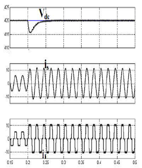
(b) Gate pulses of MOSFETs M2 and M3, Comparison of input voltage and reference voltage, Gate pulses M1, M2, M3: [X-axis: 1 div. = 0.002 s, Y-axis: 1 div. = 1 V], Voltage: [X-axis: 1 div. = 0.002 s, Y-axis: 1 div. = 100 V].


(c) Output voltage waveforms of buck-boost converter without La Output voltage of buck-boost converter and reference voltage with La: [X-axis: 1 div. = 0.02 s, Y-axis: 1 div. = 50 V], Output voltage of inverter with La: [Xaxis: 1 div. = 0.02 s, Y-axis: 1 div. = 100 V].

(d) Output voltage of buck-boost converter and inverter and inverter with La Blue color: Reference voltage, Green color: Actual output voltage of buckboost converter, Output voltage of buck-boost converter and reference voltage without La: [X-axis: 1 div. = 0.02 s, Y-axis: 1 div. = 50 V], Output voltage of inverter without La: [X-axis: 1 div. = 0.02 s, Y-axis: 1 div. = 100 V].
Fig. 4 Results for improving output voltage of inverter.


(b) Pole voltage of phase A and output of buck-boost converter compared with reference voltage of three-phase system Blue color: Reference voltage Green color: Actual output voltage of buck-boost converter for three-phase Pole voltage of phase A: [X-axis: 1 div. = 0.05 s, Y-axis: 1 div. = 50 V] Output voltage of buck-boost converter of phase A: [X-axis: 1 div. = 0.05 s,
Y-axis: 1 div. = 50 V].
Fig. 5 Simulation result of proposed three-phase topology.

CONCLUSION:
Relation between fundamental output voltage (rms) and duty ratio of switches of ac chopper operating as inverter is linear. So, on increasing the duty ratio of pulses given to switches, output voltage of inverter increases linearly. To get 100 % inverter output voltage, no need to go in over modulation region, which eliminates the non-linearity. The profile of output voltage of inverter (with chopping depending on the duty ratio of its switches) is sinusoidal because of modulated dc-link provided by the buck-boost converter, which reduces lower order harmonics, and %THD. It also reduces dv/dt as envelope of output voltage is sinusoidal as full dc-link voltage is not switched. This reduction in dv/dt reduces the stresses on the enameled copper wire of the stator winding of the motor. It will reduce the inter-turn short circuit failure of stator winding. Also this reduction of dv/dt will reduce the electromagnetic interference generated by the inverter in the drive system. In the proposed scheme, output voltage of buck-boost converter follows the reference voltage very closely for different frequencies, so when reference voltage is greater than input voltage, converter has to operate in boost mode else operates in buck mode. Hardware implementation of proposed single phase scheme is carried out. The hardware results have very close resemblance with the simulation results. The proposed concept is novel, and with appropriate refinements, can offer new era of control of inverter for V/f three-phase induction motor drive applications. However, it demands more number of power semiconductor devices compared to that needed for the conventional ac-dc-ac approach.
REFERENCES:
[1] Jose Thankachan, and Saly George, “A novel switching scheme for three phase PWM ac chopper fed induction motor,” in Proc. IEEE 5th India International Conference on Power Electronics (IICPE), pp. 1-4, 2012.
[2] Amudhavalli D., and Narendran L., “Speed control of an induction motor by V/f method using an improved Z-source inverter,” in Proc. International Conference on Emerging Trends in Electrical Engineering and Energy Management (ICETEEEM), pp. 436-440, 2012.
[3] G. W. Heumann, “Adjustable frequency control of high-speed induction motors,” Electrical Engineering, vol. 66, no. 6, pp. 576-579, June 1947. [4] Mineo Tsuji, Xiaodan Zhao, He Zhang, and Shinichi Hamasaki, “New simplified V/f control of induction motor for precise speed operation,” in Proc. International Conference on Electrical Machines and Systems (ICEMS), pp. 1-6 , 2011.
[5] V. K. Jayakrishnan, M. V. Sarin, K. Archana, and A. Chitra, “Performance analysis of MLI fed induction motor drive with IFOC speed control,” in Proc. Annual IEEE India Conference (INDICON), pp. 1-6, 2013.