ABSTRACT:
A
direct maximum power point tracking (MPPT) method for PV systems has been
proposed in this work. This method solves two of the main drawbacks of the
Perturb and Observe (P&O) MPPT, namely: i) the tradeoff between the speed
and the oscillations in steady-state, ii) the poor effectiveness in dynamic
conditions, especially in low irradiance when the measurement of signals
becomes more sensitive to noise. The proposed MPPT is designed for single-phase
single-stage grid-connected PV inverters and is based on estimating the ripple
of the instantaneous PV power and voltage, using a second-order generalized
integrator-based quadrature signal generator (SOGI-QSG). We analyzed the global
stability of the closed-loop control system and validated the proposed algorithm
through simulation and experiments on an inverter test platform according to
the EN 50530 standard. The experimental results confirm the performance of the
proposed method in terms of both speed and tracking efficiency.
KEYWORDS:
1. Single stage PV Inverter
2. Lyapunov Stability
3. MPPT
4. P&O
5. EN 50530 standard
SOFTWARE: MATLAB/SIMULINK
BLOCK DIAGRAM:
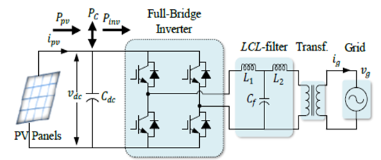
Fig.
1. System configuration of single-stage single-phase grid-connected PV system.
EXPECTED SIMULATION RESULTS:

Fig.
2. Experimental PV voltage waveforms after startup showing the convergence to
MPP with different 𝐾 values.

Fig.
3. Start waveforms comparison for DC link voltage.

Fig.
4. The output PV power under trapezoidal irradiance profile.

Fig.
5. DC link voltage under trapezoidal irradiance profile

Fig.
6. Instantanous efficiency under trapezoidal irradiance profile.

Fig.
7. Experimental start waveforms of PV power for both methods.

Fig.
8. Experimental start waveforms comparison of DC link voltage.

Fig.
9. Experimental results of PV power under trapezoidal irradiance profile.

Fig.
10. Experimental results for DC link voltage under trapezoidal irradiance
profile.

Fig.
11. Efficiency under static irradiance for both methods.

Fig.
12. PV power for P&O under dynamic irradiance profile according to EN
50530.

Fig.
13. PV power for the proposed method under dynamic irradiance profile according
to EN 50503.

Fig.
14. Efficiency comparison for the both methods from low-to-medium irradiance

Fig.
15. Efficiency comparison for the both methods from medium-to-high irradiance.
CONCLUSION:
This paper has
described the design of an effective controller for direct reaching the maximum
power point for a single-stage single-phase grid-connected PV inverter. The
proposed method has been designed based on the stability analysis using the
Lyapunov quadratic function that is formed from the variation of energy stored
in the DC link capacitor. From the simulations and experimental results on an
advanced test platform and according to the EN 50530 standard, it was confirmed
that the proposed method achieves high efficiency in both static and dynamic
conditions. Furthermore, the proposed method is very fast to reach the MPP.
[1] T. Kerekes, R.
Teodorescu, and U. Borup, “Transformerless Photovoltaic Inverters Connected to
the Grid,” APEC 07 - Twenty-Second Annual IEEE Applied Power Electronics
Conference and Exposition. pp. 1733– 1737, 2007.
[2] I. S. Kim, M.
B. Kim, and M. J. Youn, “New Maximum Power Point Tracker Using Sliding-Mode
Observer for Estimation of Solar Array Current in the Grid-Connected
Photovoltaic System,” IEEE Transactions on Industrial Electronics, vol. 53, no.
4. pp. 1027–1035, 2006.
[3] J. Selvaraj
and N. A. Rahim, “Multilevel Inverter For Grid-Connected PV System Employing
Digital PI Controller,” IEEE Transactions on Industrial Electronics, vol. 56,
no. 1. pp. 149–158, 2009.
[4] M.
Rosu-Hamzescu and S. Oprea, “Practical guide to implementing solar panel MPPT
algorithms,” Microchip Technol. Inc, 2013.
[5]
D. Sera, R. Teodorescu, J. Hantschel, and M. Knoll, “Optimized Maximum Power
Point Tracker for Fast-Changing Environmental Conditions,” IEEE Transactions on
Industrial Electronics, vol. 55, no. 7. pp. 2629–2637, 2008.


