asokatechnologies@gmail.com 09347143789/09949240245

Search This Blog

Saturday 1 June 2019

Sizing and Simulation of an Energy Sufficient Stand-alone PV Pumping System


ABSTRACT:

In this paper, methods for sizing of PV pumping systems and the simulation of (DTC) Direct Torque Control of induction motor that is used for piloting a water pump supplied by a photovoltaic generator are presented. The sizing of the PV pumping system is based on the calculation of the water needs, the required hydraulic energy and the estimation of available solar power. The best sizing of the PV pumping system may further help in reducing its cost and optimize its efficiency. The proposed system includes a solar panel, a DC/DC converter with MPPT control, a voltage inverter with pulse width modulation (PWM). The Pump is driven by a Three Phase Induction Motor. In order to control the water flow in the pump, Direct torque control of induction machine is used. The simulations are carried out in Matlab/Simulink.
KEYWORDS:

1.      MPPT
2.      DTC
3.      PV pumping
4.      Photovoltaic
5.      Three phase induction motor
6.      Induction machine (IM)
7.      Voltage inverter
8.      Pulse width modulation (PWM)

SOFTWARE: MATLAB/SIMULINK

BLOCK DIAGRAM:


Fig. 1. System block diagram
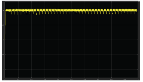
 EXPECTED SIMULATION RESULTS:


Fig. 2. Band hysteresis of flux

Fig. 3. Statoric Flux evolution
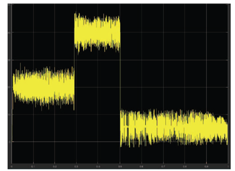
Fig. 4. Electromagnetic Torque


Fig. 5. Stator current dq Axis

Fig. 6. The motor speed


CONCLUSION:
In this paper, a case study of stand-alone PV pumping system designed for irrigation needs in a remote site in Tunisia. The sizing method for the structure was presented. MPPT technique was used to optimize the power delivered by the photovoltaic module. Direct torque control technique served to control the induction machine speed and therefore the flow of the centrifugal pump. The paper presented the system block diagram, the MPPT control algorithm, the DTC block diagram and design. The main objective of this work is to maximize savings in energy consumption by ensuring that pipelines and networks are sized and designed accurately. The use of DTC technique ensures better efficiency of the motor. The experimental results are satisfactory and suggest that the proposed solution can be a reliable option to overcome the lack of electricity at remote locations and rural areas. More reliability test and studies needs to be performed to guarantee its robustness, efficiency and cost effectiveness.

REFERENCES:
[1] “Solar resource maps for Tunisia”, Solargis S.R.O Slovakia, Maps.
[2] Chaabane. M, Ben Djemaa. A. and Kossentini, “A daily and hourly global irradiations in Tunisia extracted from Meteosat Wedax images”, Solar Energy, vol. 57, issue 6, pp. 449-457.
[3] Information obtained from the direction of the bureau of organic farming, CRDA Tozeur.
[4] T. Augustyn. “Energy efficiency and savings in pumping systems, The holistic approach”, Energy Efficiency Convention (SAEEC), 2012 Southern African.
[5] Jim McGovern, “Technical Note: Friction Factor Diagrams for Pipe Flow”, Dublin Institute of Technology, 2011.


PV-Battery Powered Direct Torque ControlledSwitched Reluctance Motor Drive


ABSTRACT:

Categorized as one of the renewable energies, Photo- Voltaic system has a great potential compared to its counterparts of renewable energies. This paper deals with the design of a Photovoltaic (PV)-Battery fed Switched Reluctance Motor(SRM). The system mainly composed of a PV module, boost converter, rechargeable battery, bidirectional converter, asymmetric bridge converter, SRM and system controllers. The main problems of SRM are high torque ripple, acoustic noise and vibration problems. In order to reduce these problems, a new direct torque control of 3.5 kW 8/6 SRM is proposed, which is simple and can be implemented with low cost processor. It can be seen from the simulation results that this scheme has well regulated the torque output of the motor with in hysteresis band. The proposed system assures its suitability for solar applications like solar vehicles, solar water pumping system and floor mills in hilly and isolated areas.
KEYWORDS:

1.      PV module
2.      Switched reluctance motor
3.      Direct torque control
4.      Battery energy storage system

SOFTWARE: MATLAB/SIMULINK

 BLOCK DIAGRAM:


Figure 1. (a)PV-Battery fed Induction Motor drive (b) PV-Battery Switched Reluctance Motor drive


 EXPECTED SIMULATION RESULTS:


Figure 2. Variation of PV output voltage and current due variation in solar
Radiation

Figure 3. Control of flux vector with in hysteresis band


Figure 4. Flux trajectory in d-q plane


Figure 5. Current waveform of different phases


Figure 6. Control of torque in hysteresis band


Figure 7. Flux waveform of different phases


CONCLUSION:

The proposed scheme reduces dc link voltage there by reducing capacitor size and insulation level. A single stage conversion is also possible without the use of boost converter. The advantage of using asymmetric bridge converter is freedom to control individual phase independently and no shoot through fault. Torque ripple in the SRM can be eliminated by Direct Torque Control technique. The results indicate that DTC of SRM can directly regulate the torque output of the motor within a hysteresis band.

 REFERENCES:

[1] Jewell W.T and Ramkumar R “The history of utility –interactive photovoltaic generation”,IEEE/PES procedings ,Vol 30 pp1-5,Feb 1988.
[2] J. Applebaum J and Sarma M.S;“The operation of permanent magnet dc motors powered by a common source of solar cells,.” IEEE Trans. On EC., ,Vol. 4, pp.635-641, dec 1989 .
[3] Putta Swamy C L, Singh Bhim and Singh B P; “Dynamic performance of permanent magnet brushless DC powered by a PV array for water pumping,. ”Journel of Solar materials and Solar cells, ,Vol. 36, No.2 pp.187-200,1995
[4] Bhat S.R, Pittet A and Sonade B S; “Performance optimization ofinduction motor pump system using photovoltaic source,.”IEEE Transon Industrial Applications., ,Vol. 23, No 6 pp.955-1000, Nov/Dec 1987.
[5] Daud, and M. Mahmoud; “Solar Power Induction Motor Drive WaterPump Operating on a Desert Well, Simulation and Field Test”,,.” IEEE Trans.on Renewable Energy, ,Vol. 30, pp.701-714,2005.

Induction Motor Drive For PV Water Pumping With Reduced Sensors


ABSTRACT:

This study presents the reduced sensors based standalone solar photovoltaic (PV) energised water pumping. The system is configured to reduce both cost and complexity with simultaneous assurance of optimum power utilisation of PV array. The proposed system consists of an induction motor-operated water pump, controlled by modified direct torque control. The PV array is connected to the DC link through a DC–DC boost converter to provide maximum power point tracking (MPPT) control and DC-link voltage is maintained by a three-phase voltage-source inverter. The estimation of motor speed eliminates the use of tacho generator/encoder and makes the system cheaper and robust. Moreover, an attempt is made to reduce the number of current sensors and voltage sensors in the system. The proposed system constitutes only one current sensor and only one voltage sensor used for MPPT as well as for the phase voltage estimation and for the phase currents’ reconstruction. Parameters adaptation makes the system stable and insensitive toward parameters variation. Both simulation and experimental results on the developed prototype in the laboratory validate the suitability of proposed system.

SOFTWARE: MATLAB/SIMULINK

CIRCUIT DIAGRAM:


Fig. 1 circuit diagram (a) Proposed system,


 EXPECTED SIMULATION RESULTS:


Fig. 2 Performance indices (a) PV array during starting to steady state at 1000 W/m2, (b) IMD indices at 1000 W/m2


Fig. 3 Performance indices during insolation change 1000–500 W/m2
(a) PV array, (b) IMD indices 500–1000 W/m2, (c) PV array (d) IMD indices


Fig. 4 Adaptation mechanism
(a) Rs adaptation at rated speed and insolation, (b) Ï„r Adaptation at rated speed and rated insolation


Fig. 5 Performance indices of the drive
(a) Starting at 1000 W/m2, (b) Starting at 500 W/m2, (c) Steady state at 1000 W/m2,
(d) Steady state at 500 W/m2


Fig. 6 Dynamic performance of the drive under variable insolation
(a) 1000–500 W/m2, (b) 500–1000 W/m2, (c) Intermediate speed signals at 1000–500
W/m2, (d) Intermediate speed signals at 500–1000 W/m2


Fig. 7 Intermediate signals in terms of
(a) Te* and Te at 1000–500 W/m2, (b) 500–1000 W/m2, (c) Reference stationary
components of flux and estimated flux at 1000–500 W/m2, (d) 500–1000 W/m2


Fig. 8 Reconstructed and measured current waveforms of phases a and b
at
(a) Starting performance at 1000 W/m2, (b) 1000 W/m2, (c) 500 W/m2, (d) Boost
converter parameters at 1000 W/m2

CONCLUSION:
The modelling and simulation of the proposed system has been carried out in MATLAB/Simulink and its suitability is validated experimentally on a developed prototype in the laboratory. The system comprises of one voltage sensor and one current sensor, which are sufficient for the proper operation of the proposed system. The motor-drive system performs satisfactorily during starting at various insolations, steady-state, dynamic conditions represented by changing insolation. The speed estimation has been carried out by flux components in stationary frame of reference. The flux and torque are controlled separately. Therefore, successful observation of the proposed system with satisfactory performance has been achieved without the mechanical sensors. This topology improves the stability of the system. The stability of the system at rated condition toward stator resistance variation is shown by Nyquist stability curve and the stability toward the rotor-time constant perturbation is shown by Popov's criteria. The DTC of an induction motor with fixed frequency switching technique reduces the torque ripple. The line voltages are estimated from this DC-link voltage. Moreover, the reconstruction of three-phase stator currents has been successfully carried out from DC-link current. Simulation results are well validated by test results. Owing to the virtues of simple structure, control, cost-effectiveness, fairly good efficiency and compactness, it is inferred that the suitability of the system can be judged by deploying it in the field.

REFERENCES:
[1] Masters, G.M.: ‘Renewable and efficient electric power systems’ (IEEE Press,Wiley and Sons, Inc., Hoboken, New Jersey, 2013), pp. 445–452
[2] Foster, R., Ghassemi, M., Cota, M.: ‘Solar energy: renewable energy and the environment’ (CRC Press, Taylor and Francis Group, Inc., Boca Raton, Florida, 2010)
[3] Parvathy, S., Vivek, A.: ‘A photovoltaic water pumping system with high efficiency and high lifetime’. Int. Conf. Advancements in Power and Energy (TAP Energy), Kollam, India, 24–26 June 2015, pp. 489–493
[4] Shafiullah, G.M., Amanullah, M.T., Shawkat Ali, A.B.M., et al.: ‘Smart grids: opportunities, developments and trends’ (Springer, London, UK, 2013)
[5] Sontake, V.C., Kalamkar, V.R.: ‘Solar photovoltaic water pumping system – a comprehensive review’, Renew. Sustain. Energy Rev., 2016, 59, pp. 1038– 1067