asokatechnologies@gmail.com 09347143789/09949240245

Search This Blog

Monday 28 February 2022

Grid Interactive Bidirectional Solar PV Array Fed Water Pumping System

 ABSTRACT:

This paper proposes a grid interactive bidirectional solar water pumping system using a three phase induction motor drive (IMD). A single phase voltage source converter (VSC) is used to direct the flow of power from grid supply to the pump and back to the grid from SPV array. A boost converter is used for the maximum power point tracking (MPPT) of the SPV array. A smart power sharing control is proposed, with preference given to the power from SPV array over the grid power. Moreover, the grid input power quality is also improved. Various modes of operation of the pump are elaborated and the performance of the system at starting, in steady state and dynamic conditions are simulated. The simulated results show the novelty and the satisfactory performance of the system.

KEYWORDS:

1.      Solar water pump

2.      MPPT

3.      Grid interactive

4.      Smart power sharing

SOFTWARE: MATLAB/SIMULINK

 BLOCK DIAGRAM:


Fig. 1. Configuration for the single phase grid interactive SPV water pumping system

 EXPECTED SIMULATION RESULTS:


Fig. 2(a) Starting performance of the proposed system in mode I


Fig. 2(b) Steady state performance of the proposed system in mode I

Fig. 2(c) Performance of the system in mode I under decreasing radiation from 800 W/m2 to 500 W/m2


 Fig. 2(d) Performance of the system in mode I under increasing radiation from 500 W/m2 to 800 W/m2


Fig. 3(a) Starting performance of the system in mode II


Fig. 3(b) Steady state performance of the system in mode II


Fig. 4(a) Characteristics of the system in mode III with decrease in Radiation


Fig. 4(b) Characteristics of the system in mode III with increase in Radiation


Fig. 5(a) Characteristics of the system in mode IV with increase in Radiation


 Fig. 5 (b) Characteristics of the system in mode III with decrease in radiation

CONCLUSION:


A single phase grid interactive solar water pumping is presented in the paper. Various modes of operation are identified and simulated in MATLAB Simulink environment. The simulated results have demonstrated the satisfactory performance of the system at starting, and in steady and dynamic conditions. The proposed system not only is able to share the power between two sources but it also improves the quality of power drawn. Moreover, the system manages to feed the power from the SPV array as in when required. The system is well suited for the rural and agricultural usage.

REFERENCES:

[1] J. Zhu, “Application of Renewable Energy,” in Optimization of Power System Operation, Wiley-IEEE Press, 2015, p. 664.

[2] Z. Ying, M. Liao, X. Yang, C. Han, J. Li, J. Li, Y. Li, P. Gao, and J. Ye, “High-Performance Black Multicrystalline Silicon Solar Cells by a Highly Simplified Metal-Catalyzed Chemical Etching Method,” IEEE J. Photovolt., vol. PP, no. 99, pp. 1–06, 2016.

[3] M. Steiner, G. Siefer, T. Schmidt, M. Wiesenfarth, F. Dimroth, and A. W. Bett, “43% Sunlight to Electricity Conversion Efficiency Using CPV,” IEEE J. Photovolt., vol. PP, no. 99, pp. 1–5, 2016.

[4] M. Kolhe, J. C. Joshi, and D. P. Kothari, “Performance analysis of a directly coupled photovoltaic water-pumping system,” IEEE Trans. Energy Convers., vol. 19, no. 3, pp. 613–618, Sep. 2004.

[5] S. R. Bhat, A. Pittet, and B. S. Sonde, “Performance Optimization of Induction Motor-Pump System Using Photovoltaic Energy Source,” IEEE Trans. Ind. Appl., vol. IA-23, no. 6, pp. 995–1000, Nov. 1987.


Fuzzy Logic Based MPPT Control for a PV/Wind Hybrid Energy System

 ABSTRACT:

In this paper, we present a modeling and simulation of a standalone hybrid energy system which combines two renewable energy sources, solar and wind, with an intelligent MPPT control based on fuzzy logic to extract the maximum energy produced by the two PV and Wind systems. Moreover, other classical MPPT methods were simulated and evaluated to compare with the FLC method in order to deduce the most efficient in terms of rapidity and oscillations around the maximum power point, namely Perturb and Observe (P&O), Incremental Conductance (INC) for the PV system and Hill Climbing Search (HCS) for the Wind generator. The simulation results show that the fuzzy logic technique has a better performance and more efficient compared to other methods due to its fast response, the good energy efficiency of the PV/Wind system and low oscillations during different weather conditions.

KEYWORDS:

1.      Hybrid energy system

2.      MPPT

3.      Fuzzy Logic Control (FLC)

4.      Wind system

5.      Photovoltaic system

6.      PMSG

SOFTWARE: MATLAB/SIMULINK

 BLOCK DIAGRAM:


 Fig. 1. Block diagram of fuzzy logic MPPT controller for PV system.

 EXPECTED SIMULATION RESULTS:


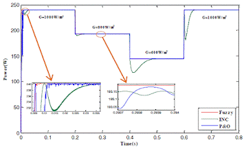
Fig. 2. PV generator output power for different MPPT techniques.


Fig. 3. PV generator output voltage for different MPPT techniques.


Fig. 4. Mechanical power of wind turbine for different MPPT techniques.


Fig. 5. Power coefficient (Cp) for different MPPT techniques.


CONCLUSION:

 In this work, an intelligent control based on fuzzy logic is developed to improve the performance and reliability of a PV/Wind hybrid energy system, also the implementation of the other conventional MPPT algorithms for compared with the FLC technique. For a best performance analysis of MPPT techniques on the system, the simulations are carried out under different operating conditions. Simulation results show that the fuzzy controller has a better performance because it allows with a fast response and high accuracy to achieve and track the maximum power point than the P&O, INC and HCS methods for the PV and Wind generators respectively.

REFERENCES:

 [1] A.V. Pavan Kumar, A.M. Parimi and K. Uma Rao, “Implementation of MPPT control using fuzzy logic in solar-wind hybrid power system,” IEEE International Conference on Signal Processing, Informatics, Communication and Energy Systems (SPICES), India, 19-21 February, 2015.

[2] C. Marisarla and K.R. Kumar, “A hybrid wind and solar energy system with battery energy storage for an isolated system,” International Journal of Engineering and Innovative Technology, vol. 3, n°3, pp. 99-104, ISSN 2277-3754, September 2013.

[3] L. Qin and X. Lu, “Matlab/Simulink-based research on maximum power point tracking of photovoltaic generation,” Physics Procedia, 24, pp.10- 18, 2012.

[4] B. Bendib, F. Krim, H. Belmili, M. F. Almi and S. Boulouma, “Advanced fuzzy MPPT controller for a stand-alone PV system,” Energy Procedia, 50, pp.383-392, 2014.

[5] H. Bounechba, A. Bouzid, K. Nabti and H. Benalla, “Comparison of perturb & observe and fuzzy logic in maximum power point tracker for pv systems,” Energy Procedia, 50, pp.677-684, 2014.

Five-Level Reduced-Switch-Count Boost PFC Rectifier with Multicarrier PWM

 ABSTRACT:

A multilevel boost PFC (Power Factor Correction) rectifier is presented in this paper controlled by cascaded controller and multicarrier pulse width modulation technique. The presented topology has less active semiconductor switches compared to similar ones reducing the number of required gate drives that would shrink the manufactured box significantly. A simple controller has been implemented on the studied converter to generate a constant voltage at the output while generating a five-level voltage waveform at the input without connecting the load to the neutral point of the DC bus capacitors. Multicarrier PWM technique has been used to produce switching pulses from control signal at a fixed switching frequency. Multi-level voltage waveform harmonics has been analyzed comprehensively which affects the harmonic contents of input current and the size of required filters directly. Full experimental results confirm the good dynamic performance of the proposed five-level PFC boost rectifier in delivering power from AC grid to the DC loads while correcting the power factor at the AC side as well as reducing the current harmonics remarkably.

KEYWORDS:

1.      Multilevel Converter

2.      Active Rectifier

3.      Multicarrier PWM

4.      Cascaded Control

5.      Power Quality

SOFTWARE: MATLAB/SIMULINK

 BLOCK DIAGRAM:


                                            Fig. 1. Proposed five-level boost PFC rectifier with reduced number of switches

EXPECTED SIMULATION RESULTS:


Fig. 2. Experimental results from steady-state operation of the rectifier


Fig. 3. Experimental results during 50% increase in the load


Fig. 4. Experimental results during AC source voltage variation


Fig. 5. Experimental results during 25% raise in the DC voltage reference


CONCLUSION:

 In this paper a reduced switch count 5-level boost PFC rectifier has been presented. A cascaded PI controller has been designed to regulate the output DC voltage and to ensure the unity power factor mode of the input AC voltage and current. Moreover, low harmonic AC current waveform has been achieved by the implemented controller and employing a small inductive filter at the input line. One of the main issues of switching rectifiers is the high switching frequency that has been reduced in this work using PWM technique through adopting multicarrier modulation scheme. Moreover, DC capacitors middle point has not been connected to the load that had required splitting the load to provide a neutral point. Using a single load with no neutral point makes this topology practical in real applications. Comprehensive experimental tests including change in the load, AC voltage fluctuation and generating different DC voltage values have been performed to ensure the good dynamic performance of the rectifier, adopted controller and switching technique. Moreover, the low THD of the input current has been measured to validate the advantage of multilevel waveforms in reducing harmonic contents and consequently diminishing the size of required filters at the input of the converters.

REFERENCES:

[1] B. Singh, B. N. Singh, A. Chandra, K. Al-Haddad, A. Pandey, and D. P. Kothari, "A review of three-phase improved power quality AC-DC converters," Industrial Electronics, IEEE Transactions on, vol. 51, no. 3, pp. 641-660, 2004.

[2] M. Mobarez, M. Kashani, and S. Bhattacharya, "A Novel Control Approach For Protection of Multi-Terminal VSC Based HVDC Transmission System Against DC Faults," IEEE Trans. Ind. Applications, vol. PP, no. 99, pp. 1-1, 2016.

[3] H. Mortazavi, H. Mehrjerdi, M. Saad, S. Lefebvre, D. Asber, and L. Lenoir, "A Monitoring Technique for Reversed Power Flow Detection With High PV Penetration Level," IEEE Trans. Smart Grid, vol. 6, no. 5, pp. 2221-2232, 2015.

[4] H. Abu-Rub, M. Malinowski, and K. Al-Haddad, Power electronics for renewable energy systems, transportation and industrial applications: John Wiley & Sons, 2014.

[5] H. Vahedi, H. Y. Kanaan, and K. Al-Haddad, "PUC converter review: Topology, control and applications," in IECON 2015-41st Annual Conference of the IEEE Industrial Electronics Society, Japan, 2015, pp. 4334-4339.

Sunday 27 February 2022

Evaluation of Battery System for Frequency Control in Interconnected Power System with a Large Penetration of Wind Power Generation

ABSTRACT:

Recently, a lot of distributed generations such as wind power generation are going to be installed into power systems. However, the fluctuation of these generator outputs affects the system frequency. Therefore, introduction of battery system to the power system has been considered in order to suppress the fluctuation of the total power output of the distributed generation. For frequency analysis, we use the interconnected 2-area power system model. It is assumed that a small control area with a large penetration of wind power plants is interconnected into a large control area. In this system, the tie line power fluctuation is very large as well as the system frequency fluctuation. It is shown that the installed battery can suppress these fluctuations and that the effect of battery on suppression of fluctuations depends on the battery capacity. Then, the required battery capacity for suppressing the tie line power deviation within a given level is calculated.

KEYWORDS:

1.      Battery

2.      Distributed Generation

3.      Frequency

4.      Load Frequency Control (LFC)

5.      Power System

6.      Tie Line Power

7.      Wind Power Generation

SOFTWARE: MATLAB/SIMULINK

BLOCK DIAGRAM:


Fig. 1. Battery system model.

EXPECTED SIMULATION RESULTS:


(a) Tie line power flow


(b) system frequency (Area 2)

Fig. 2. Impact of LFC control method.


(a)     Tie lie power flow


(b) System frequency (Area 2)


(c) Battery output

Fig. 3. Behaviors of tie line power flow, system frequency and battery

output with/without battery (Kb = 0.5, Tb = 0.5).


                                                                                     (a) Tie line power flow


(b) Battery stored energy

(c) Battery output

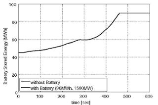
Fig. 4 Behaviors of tie line power and output and stored energy of battery (9OMWh, 1500MW)

CONCLUSION:


In this paper, we have analyzed the impact of installed wind power generation and battery on the system frequency and the tie line power. In 2-area power systems, the tie line power fluctuation is remarkably large as well as the system frequency fluctuation. It has been made clear that the installed battery can suppress these fluctuations and that the effect of battery on suppression of these fluctuations depends on battery capacity. If the stored energy of battery reaches the full capacity, the battery output changes to zero suddenly and the large fluctuation is caused. Therefore, the stored energy needs to be controlled within the rated storage capacity. Based on this need, the required battery capacity for suppressing the tie line power deviation within a reference level has been calculated. If battery and LFC generator are controlled cooperatively, installation of battery with a larger capacity makes it possible to decrease LFC capacity of the conventional generators. In the near future, a new method to calculate the optimal battery storage capacity (MWh) and the appropriate power converter capacity (MW) for various kinds of wind power generation patterns and an effective control method of the battery system for reducing the battery capacity and LFC capability of the conventional power plants will be studied.

REFERENCES:

[1] W. El-Khattam and M. M. A. Salama, "Distributed generation technologies, definitions and benefits," Electric Power Systems Research, vol. 71, issue 2, pp. 1 19-128, Oct. 2004.

[2] N. Jaleeli, L. S. VanSlyck, D. N. Ewart, L. H. Fink, and A. G. Hoffmann, "Understanding automatic generation control," IEEE Trans. Power Syst., vol. 7, pp. 1106-1122, Aug. 1992.

[3] A. Murakami, A. Yokoyama, and Y. Tada, "Basic study on battery capacity evaluation for load frequency control (LFC) in power system with a large penetration of wind power generation," T. IEE Japan, vol. 126-B, no. 2, pp. 236-242, Feb. 2006. (in Japanese)

[4] P. Kunder, "Power System Stability and Control, " McGraw-Hill, 1994.

[5] A. J. Wood and B. F. Wollenberg, "Power Generation Operation and Control," 2nd ed., Wiley, New York, 1966.


Saturday 26 February 2022

Direct Torque Control using Switching Table for Induction Motor Fed by Quasi Z-Source Inverter

 ABSTRACT:

Z-source inverters eliminate the need for front-end DC-DC boost converters in applications with limited DC voltage such as solar PV, fuel cell. Quasi Z-source inverters offer advantages over Z-source inverter, such as continuous source current and lower component ratings. In this paper, switching table based Direct Torque Control (DTC) of induction motor fed by quasi Z-Source Inverter (qZSI) is presented. In the proposed technique, dc link voltage is boosted by incorporating shoot through state into the switching table. This simplifies the implementation of DTC using qZSI. An additional DC link voltage hysteresis controller is included along with torque and flux hysteresis controllers used in conventional DTC. The results validate the boost capability of qZSI and torque response of the DTC.

KEYWORDS:

1.      DTC

2.      qZSI

3.      DC-DC Converter

4.      DC Link Voltage

5.      Hysteresis Controller

SOFTWARE: MATLAB/SIMULINK

BLOCK DIAGRAM:


Fig. 1: Block Diagram for DTC using Qzsi

EXPECTED SIMULATION RESULTS:


 Fig. 2: Torque vs. Time


Fig. 3: Stator Phase 'a' Current


Fig. 4: Speed vs. Time


Fig. 5: DC Link Voltage


Fig. 6: Capacitor Voltage, VC1

CONCLUSION:

 In this paper, direct torque control of induction motor fed by qZSI is presented. Dynamic torque response for step change obtained is 3 ms, which is needed for high performance applications. qZSI provides a single stage solution for drives with variable input DC voItage, instead of DC-DC converter cascaded with 3-leg inverter bridge. This paper presents a solution for drives with lesser DC input voItage availability and also requiring very fast torque response. The results shows that by introducing shoot through state in switching table of direct torque control, DC link voItage in qZSI is boosted. The DC link voItage hysteresis controller uses the input and capacitor voItage for controlling DC link voItage. If there is any disturbance in input voItage, the reference for capacitor voItage will be changed accordingly to maintain the DC link voItage.

REFERENCES:

 [1] 1. Takahashi and Y. Ohmori, "High-performance direct torque control of an induction motor, " IEEE Trans. Ind. Appl., vol. 25, no. 2, pp. 257-264, 1989.

[2] B.-S. Lee and R. Krishnan, "Adaptive stator resistance compensator for high performance direct torque controlled induction motor drives, " in Industry Applications Conference, 1998. Thirty-Third lAS Annual Meeting. The 1998 IEEE, vol. I, Oct 1998, pp. 423-430 voLl.

[3] G. Buja and M. Kazmierkowski, "Direct torque control of pwm inverter-fed ac motors-a survey, " IEEE Trans. Ind. Electron., vol. 51, no. 4, pp. 744-757, Aug 2004.

[4] F. Z. Peng, "Z-source inverter, " IEEE Trans. Ind. Appl., vol. 39, no. 2, pp. 504-510, Mar 2003.

[5] F. Z. Peng, A. Joseph, J. Wang, M. Shen, L. Chen, Z. Pan, E. Ortiz-Rivera, and Y. Huang, "Z-source inverter for motor drives, " IEEE Trans. Power Electron., vol. 20, no. 4, pp. 857-863, July 2005.