asokatechnologies@gmail.com 09347143789/09949240245

Search This Blog

Saturday, 6 December 2014

FLC-Based DTC Scheme to Improve the Dynamic Performance of an IM Drive

FLC-Based DTC Scheme to Improve the
Dynamic Performance of an IM Drive

ABSTRACT:
This paper presents a fuzzy logic hysteresis comparator-based direct torque control (DTC) scheme of an induction motor (IM) under varying dynamic conditions. The fuzzy logic controller (FLC) is used to adjust the bandwidth of the torque hysteresis controller in order to reduce the torque and flux ripples and, hence, to improve motor dynamic response. The effects of torque hysteresis bandwidth on the amplitude of torque ripples of an IM are also discussed in this paper. Based on the slopes of motor-estimated torque and stator current, an FLC is designed to select the optimum bandwidth of the torque hysteresis controller. This paper also proposes a simpler algorithm than the conventional trigonometric function-based algorithm to evaluate the sector number (required for DTC scheme) of the stator flux-linkage space vector. The proposed algorithm reduces the computational burden on the microprocessor. In order to test the performance of the proposed FLC-based DTC scheme for IM drive, a complete simulation model is developed using MATLAB/ Simulink. The proposed FLC-based DTC scheme is also implemented in real time using DSP board DS1104 for a prototype 1/3 hp motor. The performance of the proposed drive is tested in both simulation and experiment.

KEYWORDS:
1          Direct torque control (DTC)
2          Field-oriented control(FOC)
3          Fuzzy logic controller (FLC)
4          Induction motor (IM)
5          Torque and flux hysteresis controllers
6          Torque ripples

SOFTWARE: MATLAB/SIMULINK

CONVENTIONAL BLOCK DIAGRAM:


 Fig. 1. Conventional DTC scheme for IM drive.


SIMULATION RESULTS:

Fig. 2. Steady-state speed responses of the IM drive for a step change in load from 0.3 to 0.8 N · m at 120 rad/s. (a) Conventional DTC. (b) FLC-based DTC.


Fig. 3. Developed torque responses of the IM drive for a step change in load from 0.3 to 0.8 N · m at speed of 120 rad/s. (a) Conventional DTC. (b) FLC-based DTC scheme.


Fig. 4. Developed torque of the IM drive at 40% of rated load. The step change in speed from 100 to 150 rad/s is applied at 0.15 s. (a) Conventional DTC. (b) FLC-based DTC scheme.


Fig. 5. Steady-state stator flux-linkage responses of the IM drive, at 40% rated load and speed of 120 rad/s. (a) Conventional DTC. (b) Proposed FLCbased DTC scheme.


Fig. 6. Steady-state stator current response of the IM drive at 40% rated load and speed of 120 rad/s. (a) Conventional DTC. (b) FLC-based DTC scheme.


CONCLUSION:
A novel FLC-based DTC scheme for IM drive has been presented in this paper. The proposed FLC-based IM drive has been successfully implemented in real time using DSP board DS1104 for a laboratory 1/3 hp IM. The FLC is used to adapt the bandwidth of the torque hysteresis controller in order to reduce the torque ripple of the motor. A performance comparison of the proposed FLC-based DTC scheme with a conventional DTC scheme has also been provided both in simulation and experiment. Comparative results show that the torque ripple of the proposed drive has considerably been reduced. The dynamic speed response of the proposed FLC-based DTC scheme has also been found better as compared to the conventional DTC scheme.

 REFERENCES:
[1] I. Takahashi and T. Nouguchi, “A new quick response and high efficiency control strategy for an induction motor,” IEEE Trans. Ind. Appl., vol. IA- 22, no. 5, pp. 820–827, Sep. 1986.
[2] L. Tang, L. Zhong, M. F. Rahman, and Y. Hu, “A novel direct torque control for interior permanent-magnet synchronous machine drive with low ripple in torque and flux-a speed-sensorless approach,” IEEE Trans. Ind. Appl., vol. 39, no. 6, pp. 1748–1756, Sep./Oct. 2003.
[3] S. Kouro, R. Bernal, H. Miranda, C. A. Silva, and J. Rodriguez, “Highperformance torque and flux control for multilevel inverter fed induction motors,” IEEE Trans. Power Electron., vol. 22, no. 6, pp. 2116–2123, Nov. 2007.
[4] D. Casadei and T. Angelo, “Implementation of a direct torque control algorithm for induction motors based on discrete space vector modulation,” IEEE Trans. Power Electron., vol. 15, no. 4, pp. 769–777, July 2000.

[5] C.-T. Lin and C. S. G. Lee, Neural Fuzzy Systems: A Neuro-Fuzzy Synergism to Intelligent Systems. Upper Saddle River, NJ: Prentice-Hall, 1996.

Friday, 5 December 2014

Micro Wind Power Generator with Battery Energy Storage for Critical Load

Micro Wind Power Generator with Battery
Energy Storage for Critical Load

ABSTRACT:

In the micro-grid network, it is especially difficult to support the critical load without uninterrupted power supply. The proposed micro-wind energy conversion system with battery energy storage is used to exchange the controllable real and reactive power in the grid and to maintain the power quality norms as per International Electro-Technical Commission IEC- 61400-21 at the point of common coupling. The generated micro wind power can be extracted under varying wind speed and can be stored in the batteries at low power demand hours. In this scheme, inverter control is executed with hysteresis current control mode to achieve the faster dynamic switchover for the support of critical load. The combination of battery storage with micro-wind energy generation system (μWEGS), which will synthesize the output waveform by injecting or absorbing reactive power and enable the real power flow required by the load. The system reduces the burden on the conventional source and utilizes μWEGS and battery storage power under critical load constraints. The system provides rapid response to support the critical loads. The scheme can also be operated as a stand-alone system in case of grid failure like a uninterrupted power supply. The system is simulated in MATLAB/SIMULINK and results are presented.

KEYWORDS:
1.      Battery energy storage
2.      Micro-wind energy generating system
3.       Power quality.

SOFTWARE: MATLAB/SIMULINK

BLOCK DIAGRAM:


              Fig. 1. Scheme of micro-wind generator with battery storage for critical load application.

  
EXPECTED SIMULATION RESULTS:


    Fig. 2. (a) Source current. (b) Inverter injected current. (c) Load current.


                                                    Fig. 3. (a) Source current. (b) Load current. (c) Inverter-injected current.


Fig. 4. (a) DC link voltage. (b) Rectified current of wind generator.
(c) Current supplied by battery. (d) Charging-discharging of dc link capacitor.


Fig. 5. (a) Realization of transfer function. (b) Controller performance.


                                                                           Fig. 6. Source current and source voltage at PCC. 
                                

                                                                         Fig. 7. (a) Source current. (b) FFT of source current.

      
                                                                    Fig. 8. (a) Source current. (b) FFT of source current.   

                                                  Fig. 9. Active and reactive power (a) at source, (b) load, and (c) inverter.

CONCLUSION:

 The paper proposed micro-wind energy conversion scheme with battery energy storage, with an interface of inverter in current controlled mode for exchange of real and reactive power support to the critical load. The hysteresis current controller is used to generate the switching signal for inverter in such a way that it will cancel the harmonic current in the system. The scheme maintains unity power factor and also harmonic free source current at the point of common connection in the distributed network. The exchange of wind power is regulated across the dc bus having energy storage and is made available under the steady state condition. This also allows the real power flow during the instantaneous demand of the load. The suggested control system is suited for rapid injection or absorption of reactive/real power flow in the power system. The battery energy storage provides rapid response and enhances the performance under the fluctuation of wind turbine output and improves the voltage stability of the system. This scheme is providing a choice to select the most economical real power for the load amongst the available wind-battery-conventional resources and the system operates  in power quality mode as well as in a stand-alone mode.

REFERENCES:
[1] D. Graovac, V. A. Katic, and A. Rufer, “Power quality problems compensation with universal power quality conditioning system,” IEEE Trans. Power Delivery, vol. 22, no. 2, pp. 968–997, Apr. 2007.
[2] Z. Chen and E. Spooner, “Grid power quality with variable speed wind turbines,” IEEE Trans. Energy Conversion, vol. 16, no. 2, pp. 148–154, Jun. 2008. 

[3] Z. Yang, C. Shen, and L. Zhang, “Integration of stat COM and battery energy storage,” IEEE Trans. Power Syst., vol. 16, no. 2, pp. 254–262, May 2001.

Thursday, 4 December 2014

A Comparison of Soft-Switched DC-to-DC Converters for Electrolyzer Application

A Comparison of Soft-Switched DC-to-DC Converters for Electrolyzer Application

ABSTRACT:

An electrolyzer is part of a renewable energy system and generates hydrogen from water electrolysis that is used in fuel cells. A dc-to-dc converter is required to couple the electrolyzer to the system dc bus. This paper presents the design of three soft-switched high-frequency transformer isolated dc-to-dc converters for this application based on the given specifications. It is shown that LCL-type series resonant converter (SRC) with capacitive output filter is suitable for this application. Detailed theoretical and simulation results are presented. Due to the wide variation in input voltage and load current, no converter can maintain zero-voltage switching (ZVS) for the complete operating range. Therefore, a two-stage converter (ZVT boost converter followed by LCL SRC with capacitive output filter) is found suitable for this application. Experimental results are presented for the two-stage approach which shows ZVS for the entire line and load range.

KEYWORDS

1.      DC-to-DC converters
2.       Electrolyzer
3.       Renewable energy system (RES)
4.       Resonant converters

SOFTWARE: MATLAB/SIMULINK

BLOCK DIAGRAM:


Fig.1.Two-stage boost-LCL SRC with capacitive output filter.

EXPECTED SIMULATION RESULTS:


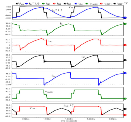
Fig.2. Simulation waveforms for LCL SRC with capacitive output filter at full-load (2.4 kW) with Vin = 40V and Vo = 60V: inverter output voltage vab ; current through resonant tank inductor iLr ; switch currents (iS1 iS4 ); rectifier input voltage (vrectin ); voltage across and current through output rectifier diode DR1 .
             

Fig.3. Simulation waveforms of Fig. 13 repeated for LCL SRC with capacitive output filter at 10% load with Vin = 40V and Vo = 60V.

CONCLUSION:

A comparison of HF transformer isolated, soft-switched, dc to- dc converters for electrolyzer application was presented. An interleaved approach with three cells (of 2.4kWeach) is suitable for the implementation of a 7.2-kW converter. Three major configurations designed and compared are as follows: 1) LCL SRC with capacitive output filter; 2) LCL SRC with inductive output filter; and 3) phase-shifted ZVS PWM full-bridge converter. It has been shown that LCL SRC with capacitive output filter has the desirable features for the present application. Theoretical predictions of the selected configuration have been compared with the SPICE simulation results for the given specifications. It has been shown that none of the converters maintain ZVS for maximum input voltage. However, it is shown that LCL-type SRC with capacitive output filter is the only converter that maintains soft-switching for complete load range at the minimum input voltage while overcoming the drawbacks of inductive output filter. But the converter requires low value of resonant inductor Lr for low input voltage design. Therefore, it is better to boost the input voltage and then use the LCL SRC with capacitive output filter as a second stage. When this converter is operated with almost fixed input voltage, duty cycle variation required is the least among all the three converters while operating with ZVS for the complete variations in input voltage and load. A ZVT boost converter with the specified input voltage (40–60 V) will generate approximately 100V as the input to the resonant converter for Vo = 60V. Therefore, we have investigated the performance of a ZVT boost converter followed by the LCL SRC with capacitive output filter. It was shown experimentally that the two-stage approach obtained ZVS for all the switches over the complete operating range and also simplified the design of resonant converter.

REFERENCES:

[1] A. P. Bergen, “Integration and dynamics of a renewable regenerative hydrogen fuel cell system,” Ph.D. dissertation, Dept. Mechanical Eng., Univ. Victoria, Victoria, BC, Canada, 2008.
[2] D. Shapiro, J. Duffy, M. Kimble, and M. Pien, “Solar-powered regenerative PEM electrolyzer/fuel cell system,” J. Solar Energy, vol. 79, pp. 544–550, 2005.
[3] F. Barbir, “PEM electrolysis for production of hydrogen from renewable energy sources,” J. Solar Energy, vol. 78, pp. 661–669, 2005.
[4] R. L. Steigerwald, “High-frequency resonant transistor DC-DC converters,” IEEE Trans. Ind. Electron., vol. 31, no. 2, pp. 181–191, May 1984.

[5] R. L. Steigerwald, “A Comparison of half-bridge resonant converter topologies,” IEEE Trans. Power Electron., vol. 3, no. 2, pp. 174–182, Apr. 1988.

Monday, 1 December 2014


Electric Springs—A New Smart Grid Technology

 ABSTRACT:

The scientific principle of “mechanical springs” was described by the British physicist Robert Hooke in the 1660’s. Since then, there has not been any further development of the Hooke’s law in the electric regime. In this paper, this technological gap is filled by the development of “electric springs.” The scientific principle, the operating modes, the limitations, and the practical realization of the electric springs are reported. It is discovered that such novel concept has huge potential in stabilizing future power systems with substantial penetration of intermittent renewable energy sources.
This concept has been successfully demonstrated in a practical power system setup fed by an ac power source with a fluctuating wind energy source. The electric spring is found to be effective in regulating the mains voltage despite the fluctuation caused by the intermittent nature of wind power. Electric appliances with the electric springs embedded can be turned into a new generation of smart loads, which have their power demand following the power generation profile. It is envisaged that electric springs, when distributed over the power grid, will offer a new form of power system stability solution that is independent of information and communication technology.

KEYWORDS:
1. Distributed power systems
2. Smart loads
3. Stability

SOFTWARE: MATLAB/SIMULINK
  
BLOCK DIAGRAM:

    Fig.1. Schematic of the experimental setup with an electric spring connected
                           in series with a resistive-inductive load Z1.

CONCLUSION:
The Hooke’s law on mechanical springs has been developed into an electric spring concept with new scientific applications for modern society. The scientific principles, operating modes and limits of the electric spring are explained. An electric spring has been practically tested for both voltage support and suppression, and for shaping load demand (of about 2.5 kW) to follow the fluctuating wind power profile in a 10 kVA power system fed by an ac power source and a wind power simulator. The electric springs can be incorporated into many existing noncritical electric loads such as water heaters and road lighting systems [26] to form a new generation of smart loads that are adaptive to the power grid.
If many non critical loads are equipped with such electric springs and distributed over the power grid, these electric springs (similar to the spring array in Fig. 1) will provide a highly reliable and effective solution for distributed energy storage, voltage regulation and damping functions for future power systems. Such stability measures are also independent of information and communication technology (ICT). This discovery based on the three-century-old Hooke’s law offers a practical solution to the new control paradigm that the load demand should follow the power generation in future power grid with substantial renewable energy sources. Unlike traditional reactive power compensation methods, electric springs offer both reactive power compensation and real power variation in the non critical loads. With many countries determined to de-carbonize electric power generation for reducing global warming by increasing renewable energy up to 20% of the total electrical power output by 2020 [22]–[25], electric spring is a novel concept that enables human society to use renewable energy as nature provides. The Hooke’s law developed in the 17th century has laid down the foundation for stability control of renewable power systems in the 21st century.

EXPECTED SIMULATION RESULTS:
 Fig. 2. Measured steady-state electric spring waveforms under “neutral” mode. Va =4.5 Vac,QES=17.5 Var. [Electric spring voltage is near zero.]
 Fig. 3. Measured steady-state electric spring waveforms under “capacitive” mode. Va =9.7.9 Vac,QES=349.9  Var. [Electric spring voltage is near zero.]
Fig. 4. Measured steady-state electric spring waveforms under “inductive” mode. Va =94.3 Vac,QES=348.4 Var. [Electric spring voltage is near zero.]

REFERENCES:
[1]Hooke’s law—Britannica Encyclopedia [Online]. Available: http:// www.britannica.com/ EB checked / topic/271336/Hookes-law
[2] A. M. Wahl, Mechanical Springs, 2nd ed. New York: McGraw-Hill, 1963.
[3] W. S. Slaughter, The Linearized Theory of Elasticity. Boston, MA: Birkhauser, 2002.
[4] K. Symon, Mechanics. ISBN 0-201-07392-7. Reading, MA: Addison- Wesley, Reading,1971.
[5] R. Hooke, De Potentia Restitutiva, or of Spring Explaining the Power of Springing Bodies. London, U.K.: John Martyn, vol. 1678, p. 23.


Power Quality and Power Interruption Enhancement by Universal Power Quality Conditioning System with Storage Device


Power Quality and Power Interruption Enhancement by Universal Power Quality Conditioning System with Storage Device

 Abstract: In this paper a novel design of Universal Power Quality Conditioning System (UPQS) is proposed which is composed of the DC/DC converter and the storage device connected to the DC link of UPQS for balancing the voltage interruption. The proposed UPQS can balance the reactive power, harmonic current, voltage sag and swell, voltage unbalance, and the voltage interruption. The performance of proposed system was analyzed through simulations with MATLAB\SIMULINK software. The proposed system can improve the power quality at the common connection point of the non-linear load and the sensitive load.

Keywords:
1.      Universal Power Quality Conditioning System (UPQS)
      2.      Voltage interruption
      3.      DC/DC converters
      4.      uper-capacitor

Software: MATLAB/SIMULINK

Block Diagram:
           Fig. 1: Configuration of proposed UPQC with energy storage.

Expected Simulation Results:
         
                                                                              Fig. 2: Nonlinear load current
                                                Fig. 3: Active and reactive power consumed by load.


                                            Fig. 4: Voltage sag compensation. (a) Source voltage. (b) Load voltage.

Conclusion:
This paper proposes a new configuration of UPQC that consists of the DC/DC converter and the super capacitors for compensating the voltage interruption. The proposed UPQC can compensate the reactive power, harmonic current, voltage sag and swell, voltage unbalance, and the voltage interruption. The control strategy for the proposed UPQC was derived based on the Synchronous reference frame method. The operation of proposed system was verified through simulations with MATLAB/SIMULINK software. The proposed UPQC has the ultimate capability of improving the power quality at the installation point in the distribution system. The proposed system can replace the UPS, which is effective for the long duration of voltage interruption, because the long duration of voltage interruption is very rare in the present power system.

 References:
[1]           Akagi, H., Y. Kanazawa and A. Nabae, 2007. Instantaneous reactive power compensator comprising switching devices without energy storage components. IEEE Transactions on Industry Application, 20: 625-630.
[2]           Aredes, M., K. Heumann, E.H. Watanabe, 1998. An universal active power line conditioner. IEEE Transactions on Power Delivery, 13(2): 545-551.
[3]           Aredes, M. and E.H. Watanabe, 1995. New control algorithms for series and shunt three-phase four-wire active power Filters. IEEE Transactions on Power Delivery, 10: 1649-1656.
[4]           Arrillaga, J., M.H.J. Bollen, N.R. Watson, 2000. Power quality following deregulation. Proceedings of the IEEE, 88(2): 246-261.
[5]           Bendre, A., S. Norris, D. Divan, I. Wallace, 2003. New high power DC/DC converter with loss limited switching and lossless secondary clamp. IEEE Transactions on Power Electronics, 18(4):1020-1027.
[6]           Han, B., B. Bae, H. Kim, S. Baek, 2006. Combined Operation of Unified Power Quality Conditioner With Distributed Generation. IEEE Transactions on Power Delivery, 21: 330-338.
[7]           Han, B., B. Bae, S. Baek, G. Jang, 2006. New configuration of UPQC (unified power quality conditioner) for medium-voltage application. IEEE Transactions on Power Delivery, 21(3): 1438-1444.
[8]           Hideaki, F. and A. Hirofumi, 1998. The unified power quality conditioner: the integration of series- and shunt- active filters. IEEE Transactions on Power Electronics, 13(2): 315–322.
[9]           Hingorani, N.G., 1995. Introducing custom power. IEEE Spectrum, 32(6): 41- 48.
[10]         Hu, M. and H. Chen, 2000. Modeling and Controlling of Unified Power Quality Compensator. IEEE International Conference on Advances in Power System Control, Operation and Management, 2: 431-435. Jacobs, J., A. Averberg, R. De Doncker, 2004. A novel three-phase DC/DC converter for high-power applications. IEEE Power Electronics Specialists Conference, 3: 1861-1867.

[11]         Prodanovic, M., and T.C. Green, 2003. Control and filter design of three-phase inverters for high power quality grid connection. IEEE Transactions on Power Delivery, 18(1): 373-380.

Friday, 21 November 2014

A Fast Space-Vector Modulation Algorithm for Multilevel Three-Phase Converters

A Fast Space-Vector Modulation Algorithm for
Multilevel Three-Phase Converters

ABSTRACT:

This paper introduces a general space-vector modulation algorithm for -level three-phase converters. The algorithm is computationally extremely efficient and is independent of the number of converter levels. At the same time, it provides good insight into the operation of multilevel converters.

KEYWORDS:

1.      Digital control
2.       Pulse width modulation
3.       Space vectors

SOFTWARE: MATLAB/SIMULINK

 BLOCK DIAGRAM:


Fig.1.Types of multilevel converters.


Fig .2.Classification of multilevel modulations.

  CONCLUSION:

This paper has presented a fast new SVM algorithm for multilevel three-phase converters. The algorithm is general and applicable to converters with any number of levels. In addition, the number of steps required to select the nearest three vectors and compute their duty cycles remains the same regardless of the number of converter levels or the location of the reference vector. In addition, the computational efficiency of this algorithm makes it a useful simulation tool for further study of the properties of multilevel converters.

REFERENCES:

[1] L. M. Tolbert and F. Z. Peng, “Multilevel converters for large electric drives,” in Proc. IEEE APEC’98, vol. 2, 1998, pp. 530–536.
[2] Y. Chen, B. Mwinyiwiwa, Z. Wolanski, and B.-T. Ooi, “Regulating and equalizing dc capacitance voltages in multilevel statcom,” IEEE Trans. Power Delivery, vol. 12, pp. 901–907, Apr. 1997.
[3] J.-S. Lai and F. Z. Peng, “Multilevel converters—A new breed of power converters,” IEEE Trans. Ind. Applicat., vol. 32, pp. 509–517, May/June 1996.
[4] P. M. Bhagwat and V. R. Stefanovic, “Generalized structure of a multilevel PWM inverter,” IEEE Trans. Ind. Applicat., vol. IA-19, pp. 1057–1069, Nov./Dec. 1983.
[5] G. Sinha and T. A. Lipo, “A four level rectifier-inverter system for drive applications,” IEEE Trans. Ind. Applicat., vol. 30, pp. 938–944, July/Aug. 1994.