ABSTRACT:
Two high static gain step-up dc–dc converters based on
the modified SEPIC converter are presented in this paper. The proposed
topologies present low switch voltage and high efficiency for low input voltage
and high output voltage applications. The configurations with magnetic coupling
and without magnetic coupling are presented and analyzed. The magnetic coupling
allows the increase of the static gain maintaining a reduced switch voltage. The
theoretical analysis and experimental results show that both structures are
suitable for high static gain applications as a renewable power sources with
low dc output voltage. Two experimental prototypes were developed with an input
voltage equal to 15 V and an output power equal to 100 W. The efficiency at
nominal power obtained with the prototype without magnetic coupling was equal
to 91.9% with an output voltage of 150 V. The prototype with magnetic coupling
operating with an output voltage equal to 300 V, presents an efficiency at
nominal power equal to 92.2%.
KEYWORDS:
1.
DC–DC power
conversion
2.
Voltage multiplier and solar power generation
SOFTWARE: MATLAB/SIMULINK
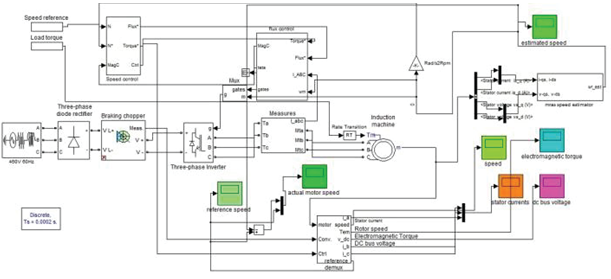
BLOCK DIAGRAM:


CONCLUSION:
Two
new topologies of non isolated high static gain converters are presented in
this paper. The first topology without magnetic coupling can operate with a
static gain higher than 10 with a reduced switch voltage. The structure with
magnetic coupling can operate with static gain higher than 20 maintaining low
the switch voltage. The efficiency of proposed converter without magnetic
coupling is equal to 91.9% operating with input voltage equal to 15 V, output
voltage equal 150 V, and output power equal 100 W. The efficiency of the
proposed converter with magnetic coupling is equal to 92.2% operating with
input voltage equal to 15V, output voltage equal 300V, and output power equal
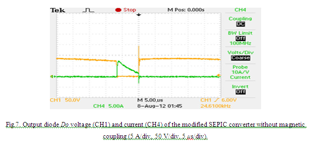
100W. The commutation losses of the proposed converter with magnetic coupling
are reduced due to the presence of the transformer leakage inductance and the
secondary voltage multiplier that operates as a nondissipative clamping circuit
to the output diode voltage.
REFERENCES:
[1] C. W. Li and X. He, “Review of
non-isolated high step-up DC/DC converters in photovoltaic grid-connected
applications,” IEEE Trans. Ind. Electron., vol. 58, no. 4, pp.
1239–1250, Apr. 2011.
[2]
C. S. B. Kjaer, J. K. Pedersen, and F. Blaabjerg, “A review of singlephase grid-connected
inverters for photovoltaic modules,” IEEE Trans. Ind. Appl., vol.
41, no. 5, pp. 1292–1306, Sep. 2005.
[3]
D. Meneses, F. Blaabjerg, O. Garcia, and J. A. Cobos, “Review and comparison of
step-up transformerless topologies for photovoltaic AC-Module application,” IEEE
Trans. Power Electron., vol. 28, no. 6, pp. 2649–2663, Jun. 2013.
[4]
D. Zhou, A. Pietkiewicz, and S. Cuk, “A Three-Switch high-voltage converter,” IEEE
Trans. Power Electron., vol. 14, no. 1, pp. 177–183, Jan. 1999.
[5]
M. Prudente, L. L. Pfitscher, G. Emmendoerfer, E. F. Romaneli, and R. Gules,
“Voltage multiplier cells applied to non-isolated DC–DC converters,” IEEE
Trans. Power Electron., vol. 23, no. 2, pp. 871–887, Mar. 2008.