asokatechnologies@gmail.com 09347143789/09949240245

Search This Blog

Thursday, 30 October 2014

Analysis And Design Considerations Of Zero-Voltage And Zero-Current-Switching (ZVZCS) Full-Bridge PWM Converters

Analysis And Design Considerations Of Zero-Voltage And Zero-Current-Switching (ZVZCS) Full-Bridge PWM Converters

ABSTRACT

In this paper, a detailed analysis of the zero voltage and zero-current-switching (ZVZCS) full-bridge PWM converters is performed. The differences of the zero-voltage-switching (ZVS) operation between the conventional ZVS full-bridge PWM converters and the ZVZCS full-bridge PWM converters are analyzed in depth. Circuit parameters that affect the soft-switching conditions are examined and the critical parameters are identified. Based on the analysis, practical design considerations are presented. The analysis and design considerations are verified by experimental results from a 630V/4kW converter operating at 80kHz.

SOFTWARE: MATLAB/SIMULINK

CIRCUIT DIAGRAM:

 
                      Fig. 1 Circuit diagram of ZVZCS FB PWM converter


                                                Fig.2 schematic of the converter

CONCLUSION:

In this paper, the zero-voltage and zero-current-switching (ZVZCS) Full-bridge PWM converter was analyzed in depth. The difference of the zero-voltage-switching (ZVS) principle between the conventional ZVS full-bridge PWM converters and the ZVZCS full-bridge PWM converters was analyzed in detail. Circuit parameters affecting the soft switching conditions were examined and the critical parameters were identified. Based on the analysis, practical design considerations were presented. The design procedures can be applied to the various kinds of ZVZCS full-bridge PWM converters [1-5]. The analysis and design considerations were verified by experimental results from a 630V/4kW converter operating at 80kHz.


REFERENCES:

[1] E. S. Kim, K. Y. Cho, et. Al., "An improved ZVZCS PWM FB DC/DC converter using energy recovery snubber," IEEE APEC Rec., 1997, pp.1014-1019.
[2] Jung G. Cho, Ju W. Baek, D.W. Yoo, Hong S. Lee, and Geun H. Rim, "Novel Zero-Voltage and Zero-Current- Switching(ZVZCS) Full Bridge PWM Converter Using Transformer Auxiliary Winding", IEEE PESC Rec., 1997, pp. 227-232.
[3] Jung G. Cho, J. W. Baek, D.W. Yoo, H. S. Lee, and G. H. Rim, "Novel Zero-Voltage and Zero-Current- Switching(ZVZCS) Full Bridge PWM Converter Using a simple auxiliary circuit", IEEE APEC Rec., 1998, pp.834-839.
[4] E. S. Kim, K.Y. Joe and S. G. Park, "An Improved ZVZCS PWM FB DC/DC Converter Using the Modified Energy Recovery Snubber", IEEE APEC Rec., 2000, pp.119-124.

[5] H. S. Choi, J. W. Kim and B.H. Cho, “Novel-Zero- Voltage and Zero-Current-Switching(ZVZCS) Full- Bridge PWM Converter Using Coupled Output Inductor”, APEC 2001. pp.967-973

Current-Fed Dual-Bridge DC–DC Converter

Current-Fed Dual-Bridge DC–DC Converter

ABSTRACT

A new isolated current-fed pulse width modulation dc–dc converter—current-fed dual-bridge dc–dc converter—with small inductance and no dead time operation is presented and analyzed. The new topology has more than 3 smaller inductance than that of current-fed full-bridge converter, thus having faster transient response speed. Other characteristics include simple self-driven synchronous rectification, simple housekeeping power supply, and smaller output filter capacitance. Detailed analysis shows the proposed converter can have either lower voltage stress
on all primary side power switches or soft switching properties when different driving schemes are applied. A 48-V/125-W prototype dc–dc converter with dual output has been tested for the verification of the principles. Both simulations and experiments verify the feasibility and advantages of the new topology.

KEYWORDS
1.     Current-fed
2.     Dc–dc converter
3.     Dead time
4.     Dual-bridge
5.     Full-bridge
6.     Zero voltage switching (ZVS)

SOFTWARE: MATLAB/SIMULINK

CIRCUIT  DIAGRAM:

Fig. 1.Current-fed full-bridge dc–dc converter.

CONCLUSION:

A new topology, isolated current-fed dc–dc converter, characterized by small inductor and no dead time operation, is presented and analyzed. An experimental prototype with 48-V (36–62 V) input and dual outputs of 5 V/20 A and 12.5 V/2 A verifies the validity and merits of the new topology. It has small inductor (corresponding to faster transient response speed), and no RHP zero in its transfer characteristic. Its output ripple current is smaller in contrast to other current-fed topologies [1]–[10], and it has no start-up problem mentioned in [1] and [10]. The main limitations of the new topology are that six power switches are used, and that input voltage range should remain within 2:1 in order to maintain the no dead time property.

REFERENCES:

[1] L. Zhu, K. Wang, F. C. Lee, and J. S. Lai, “New start-up schemes for isolated full-bridge boost converters,” IEEE Trans. Power Electron., vol. 18, no. 4, pp. 946–951, Jul. 2003.
[2] V. Yakushev, V. Meleshin, and S. Fraidlin, “Full-bridge isolated current fed converter with active clamp,” in Proc. IEEE Appl. Power Electron. Conf., 1999, pp. 560–566.
[3] K. Wang, F. C. Lee, and J. Lai, “Operation principles of bi-directional full-bridge dc–dc converter with unified soft-switching scheme and soft-starting capability,” in Proc. IEEE PESC, 2000, pp. 111–118.
[4] P. Tenti, L. Rossetto, L. Malesani, R. Borgatti, and R. Stefani, “Single stage current-fed dc–dc converter with time-sharing control of output voltage and input current,” IEEE Trans. Power Electron., vol. 5, no. 4, pp. 389–397, Oct. 1990.
[5] R. Borgatti, R. Stefani, O. Bressan, F. Bicciato, P. Tenti, and L. Rossetto, “1 kW, 9 kV dc–dc converter module with time-sharing control of oupout voltage and input current,” IEEE Trans. Power Electron., vol.8, no. 4, pp. 606–614, Oct. 1993.


An Improved Power-Quality 30-Pulse AC–DC for Varying Loads


An Improved Power-Quality 30-Pulse AC–DC for Varying Loads

 ABSTRACT

This paper presents the design and analysis of a novel 30-pulse ac–dc converter for harmonic mitigation under varying loads. The proposed 30-pulse ac-dc converter is based on a polygon-connected autotransformer with reduced magnetics. The proposed ac–dc converter is able to eliminate lower than29th order harmonics in the ac supply current. The resulting supply current is near sinusoidal in shape with low total harmonic distortion and a nearly unity power factor. Moreover, the design of an autotransformer is modified to make it suitable for retrofit applications, where converter is found to be suitable for retrofit applications with a large load

KEYWORDS:
1. Autotransformer
2. Multi pulse ac–dc converter
3. Polygon connection
4. power-quality (PQ) improvement.

SOFTWARE: Matlab/Simulink


SCHEMATIC DIAGRAM:


     Fig.1 Six-pulse diode-bridge rectifier fed load (topology “A”).


                Fig.2.  Proposed  30-pulse ac–dc converter-fed varying load (topology B).


CONCLUSION:

A new 30-pulse ac–dc converter-feeding varying load has been designed, modeled, simulated, and developed to demonstrate its improved performance. The proposed 30-pulse ac–dc converter consists of a reduced rating polygon-connected autotransformer for producing the desired phase shifted voltages and is suitable for retrofit applications, where presently a 6-pulse diode-bridge rectifier is used. It has resulted in the elimination of a lower than 29th harmonic in the supply current. The proposed ac–dc converter has resulted in a THD of supply current of less than 5% in a wide operating range of the load with nearly unity power factor operation. The proposed converter results in the reduction in rating of the magnetics, leading to savings in weight, size, volume, and, finally, the overall cost of the converter system. The results obtained on the developed converter configuration also validate the simulated models and the design procedure

REFERENCES:

[1] B. K. Bose, “Recent advances in power electronics,” IEEE Trans.Power Electron., vol. 7, no. 1, pp. 2–16, Jan. 1992.
[2] G. T. Heydt, Electric Power Quality. West La Fayette, IN: Stars in a Circle Publication, 1991.
[3] M. H. J. Bollen, Understanding Power Quality Problems: Voltage Sags and Interruptions. Piscataway, NJ: IEEE Press, 2000.
[4] A. Ghosh and G. Ledwich, “Power quality enhancement using custom power devices,” in. Norwell, MA: Kluwer, 2002.


Enhancement of Voltage Quality in Isolated Power Systems

Enhancement of Voltage Quality in Isolated Power Systems

ABSTRACT

The use of series compensators (SCs) in improving voltage quality of isolated power systems is considered. The roles of the compensators are to mitigate the effects of momentary voltage sags/swells, and to control the level of harmonic distortions in the networks. A control strategy for the SC is developed to regulate power flow. This is achieved through phase adjustment of load terminal voltage. It leads to an increase in the ride through capability of loads to the voltage sags/swells. Validity of the technique is illustrated through simulation.

KEYWORDS
1.     Harmonic power flow
2.     Isolated power system
3.     phase shift
4.     Series compensation

SOFTWARE: Matlab/Simulink

BLOCK DIAGRAM:

Fig. 1.Typical isolated power system installed with an SC.

CONCLUSION:

Voltage quality improvement in an isolated power system through series compensation has been investigated. The power system contains significant proportion of fluctuating nonlinear load and a high level of harmonic distortions is observed. A method to control the injection voltage of the SC so that it can mitigate the effects of the harmonics has been proposed. The SC is also designed to maintain the fundamental frequency component of the terminal voltage of protected sensitive load. In the process of harmonic voltage compensation, it is shown that power exchange exists between the SC and the external network. Based on the analysis of the harmonic real power flow in the power system, it is seen that the SC would import harmonic real power from the external system. A new SC control strategy is then proposed which involves the phase adjustment of the fundamental frequency component of the sensitive load terminal voltage. Through the analysis on the power exchange it is shown that the load ride through capability during voltage sag can be improved with the support of the harmonic real power absorbed by the SC. The capacity of the SC required is modest and, therefore, makes it a viable device for such an application. Simulations have confirmed the effectiveness of the proposed method, as it is applied on the SC to achieve improved quality of supply in the power system.

REFERENCES:

[1] I. Jonasson and L. Soder, “Power quality on ships-a questionnaire evaluation concerning island power system,” in Proc. IEEE Power Eng. Soc. Summer Meeting, Jul. 2001, vol. 15–19, pp. 216–221.
[2] J. J. Graham, C. L. Halsall, and I. S. McKay, “Isolated power systems: Problems of waveform distortion due to thyristor converter loading,” in Proc. 4th Int. Conf. Power Electronics and Variable-Speed Drives, Jul. 1990, vol. 17–19, pp. 327–330.
[3] ITI (CBEMA) Curve Application Note, [Online]. Available: http://www.itic.org., Inf. Technol. Ind. Council (ITI).
[4] J. C. Das, “Passive filter—Potentialities and limitations,” IEEE Trans. Ind. Appl., vol. 40, no. 1, pp. 232–241, Jan. 2004.
[5] H. Akagi, “New trends in active filter for power conditioning,” IEEE Trans. Ind. Appl., vol. 32, no. 6, pp. 1312–1322, Nov. 1996.


A Novel Nine-Switch Inverter for Independent Control of Two Three-phase Loads

A Novel Nine-Switch Inverter for Independent Control of Two Three-phase Loads

ABSTRACT

Industrial applications require large numbers of motors. For example, motors are used to manipulate industrial robots, an electric vehicles with in-wheel motors and electric trains. Two methods exist for controlling PM motors providing an inverter to control each motor, and connecting the motors in parallel and driving them with a single inverter. The first method makes an experimental apparatus complex and expensive; the second does not allow independent control of each motor because of differences in rotor angle between the two motors. Thus, we propose a novel nine-switch inverter that can independently control two three-phase loads. This paper introduces the structure of the nine-switch inverter, which is made from nine switches. The
validity of the proposed inverter is verified through simulations and experiments.

BLOCK DIAGRAM:


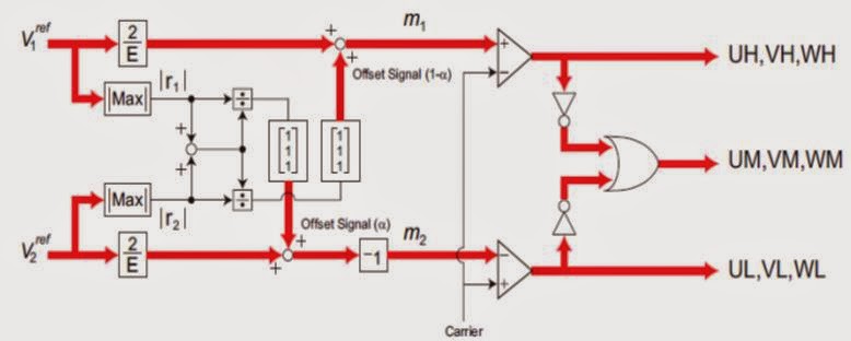
Fig. 1. Block diagram of establishment of modulation rate.

CIRCUIT DIAGRAM:


Fig. 2.Main circuit of proposed nine-switch inverter


CONCLUSION:

This paper proposes a nine-switch inverter and a PWM method that can independently control two three-phase loads. The simulations and the experiments were performed to verify the validity of the proposed inverter. The results confirmed that the nine-switch inverter can independently control amplitude and frequency for two three-phase loads, and permanent magnet synchronous motors; however, there is some ripple amplitude, and slight interference between Inv1 and Inv2. Work is needed to improve of the interference problem.

REFERENCES:

[1] Yusuke Nozawa, Motoki Hizume, Yuta Kimura, Kazuo Oka, and Kouki Matsuse, “Independent Position Control of Two Permanent Magnet Synchronous Motors with Five–Leg Inverter By the Expanded Two–Arm Modulation Method”, IEEJ Industry Applications Society Conference, 2005, (in Japanese)
[2] Tsutomu Kominami and Yasutaka Fujimoto, “Magnetic Levitation Control and Spiral-Linear Transformation System for Spiral Motor”, IEEE Int. Workshop on Advanced Motion Control, vol. 2, pp. 529-534, 2006
[3] Tsutomu Kominami and Yasutaka Fujimoto, “Proposal of a Nine-Switch Inverter That Can Independently Control Two PM Motors”, IEEJ Industry Applications Society Conference, pp. 187-190, 2006, (in Japanese)
[4] Kazuo Oka and Kouki Matsuse, “A Nine-Switch Inverter for Driving Two AC Motors Independently”, IEEJ Trans. on Electrical and Electronic Engineering, 2007
[5] Tsutomu Kominami and Yasutaka Fujimoto, “Development of a Nine- Switch Inverter That Can Independently Control Two Loads”, IEEJ Annual Meeting Record, pp. 133-134, 2007, (in Japanese)


Simulink Model of Direct Torque Control of Induction Machine

Simulink Model of Direct Torque Control of Induction Machine

ABSTRACT

 Direct torque control (DTC) is one of the most excellent control strategies of torque control in induction machine. It is considered as an alternative to the field oriented control (FOC) or vector
control technique. These two control strategies are different on the operation principle but their
objectives are the same. They aim to control effectively the torque and flux. Torque control of an
induction machine based on DTC strategy has been developed and a comprehensive study is present in this research. The performance of this control method has been demonstrated by simulations performed using a versatile simulation package, Matlab/Simulink. Several numerical simulations have been carried out in a steady state and transient operation on a speed control mode.

KEYWORDS
1. Direct torque control
2. Induction machine
3. Vector control
4. Matlab/Simulink

SOFTWARE: Matlab/Simulink

BLOCK DIAGRAM:

                        Fig.1 Direct torque control of induction machine


                  Fig. 2: Developed model of direct torque control of induction machine


CONCLUSION:

The work carried out in this paper is aimed and focused to develop a direct torque control simulink model. The DTC architecture allows the independent and decoupled control of torque and stator flux. The implementation of the DTC model has been deeply described and justified its realization. In order to show the effectiveness of the model, a numerical simulation has been performed on a 7.5 kW induction machine fed by an IGBT PWM inverter. The feasibility and the
validity of the developed DTC model, based on switching table technique, have been proved by simulation results obtained in the torque control mode.

REFERENCES:

1.     Casadei, D., G. Gandi, G. Serra and A. Tani, 1994. Effect of flux and torque hysteresis band amplitude in direct torque control of Induction Machine. Proc. IECON’94, Bologna, Italy, 299-304.
2.      Casadei, D., F. Profumo, G. Serra and A. Tani, 2002. FOC and DTC: two viable schemes for induction motors torque control. IEEE Trans. Power Electronics, 17(5): 779-787.
3.     3. Chapuis, Y.A. and D. Roye, 1998. Direct torque control and current limitation method in start up of an induction machine. IEE Conf. Power Electronics and Variable Speed Drives, 451-455
4.     4. Takahashi, I. and Y. Ohmori, 1989. High Performace direct torque control of induction motor. IEEE Trans. Ind. Appl. 25 (2): 257-264.
5.      Vas, P., 1990. Vector Control of a.c. machines.Oxford University Press.


Study on Speed Sensor less SVM-DTC System of PMSM

ABSTRACT:

A novel speed sensorless direct torque control system-SVM-DTC of permanent magnet synchronous motor(PMSM) based on SVM and MRAS is presented. In this paper the various components of the speed sensorless SVM-DTC and the principle of realization are discussed in detail. Finally the simulation results with the application of MATLAB/Simulink show that the speed identification algorithm is accurate and of robustness, moreover, the whole control system has good static and dynamic performances.

KEYWORDS:
1.      Permanent magnet synchronous motor (PMSM)
2.      Space Vector Modulation (SVM)
3.      Direct torque control (DTC)
4.      Model reference adaptive system (MRAS)

SOFTWARE: MATLAB/SIMULINK

BLOCK DIAGRAM:

CONCLUSION:
In this paper, the speed sensorless SVM-DTC system based on SVM and MRAS is presented and the control system has a clear control principle and structure. Simulation results show that the speed identification algorithm can estimate accurately the real speed and has robustness to varying of stator resistor. Moreover the speed sensorless SVM-DTC system has good static and dynamic performance.

 REFERENCES:

[1] Yen-Shin Lai, Jian-Ho Chen, A New Approach to Direct Torque Control of Induction Motor Drives for Constant Inverter Switching Frequency and Torque Ripple Reduction[J], IEEE Transactions on Energy Conversion,2001,16(3): 220-227
[2] Liang yan, Li Yongdong. The state of art of sensor-less vector control of PMSM[J]. Electric Drive,2003,33(4):4-9
[3] Young Sam Kim, Sang Kyoon Kim,Young Ahn Kwon,MRAS Based Sensorless Control of Permanent Magnet Synchronous Motor[C] . SICE Annual Conference, Fukui, Japan, 2003:1632-1637
[4] Li Yongdong. AC motor digital control system [M]. Beijing: Machine Press,2002
[5] Li Su. Direct Torque Control of Induction Motor[M]. Beijing: Machine Press,1999