asokatechnologies@gmail.com 09347143789/09949240245

Search This Blog

Sunday, 27 February 2022

Evaluation of Battery System for Frequency Control in Interconnected Power System with a Large Penetration of Wind Power Generation

ABSTRACT:

Recently, a lot of distributed generations such as wind power generation are going to be installed into power systems. However, the fluctuation of these generator outputs affects the system frequency. Therefore, introduction of battery system to the power system has been considered in order to suppress the fluctuation of the total power output of the distributed generation. For frequency analysis, we use the interconnected 2-area power system model. It is assumed that a small control area with a large penetration of wind power plants is interconnected into a large control area. In this system, the tie line power fluctuation is very large as well as the system frequency fluctuation. It is shown that the installed battery can suppress these fluctuations and that the effect of battery on suppression of fluctuations depends on the battery capacity. Then, the required battery capacity for suppressing the tie line power deviation within a given level is calculated.

KEYWORDS:

1.      Battery

2.      Distributed Generation

3.      Frequency

4.      Load Frequency Control (LFC)

5.      Power System

6.      Tie Line Power

7.      Wind Power Generation

SOFTWARE: MATLAB/SIMULINK

BLOCK DIAGRAM:


Fig. 1. Battery system model.

EXPECTED SIMULATION RESULTS:


(a) Tie line power flow


(b) system frequency (Area 2)

Fig. 2. Impact of LFC control method.


(a)     Tie lie power flow


(b) System frequency (Area 2)


(c) Battery output

Fig. 3. Behaviors of tie line power flow, system frequency and battery

output with/without battery (Kb = 0.5, Tb = 0.5).


                                                                                     (a) Tie line power flow


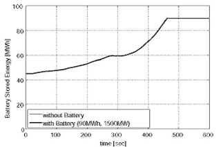
(b) Battery stored energy

(c) Battery output

Fig. 4 Behaviors of tie line power and output and stored energy of battery (9OMWh, 1500MW)

CONCLUSION:


In this paper, we have analyzed the impact of installed wind power generation and battery on the system frequency and the tie line power. In 2-area power systems, the tie line power fluctuation is remarkably large as well as the system frequency fluctuation. It has been made clear that the installed battery can suppress these fluctuations and that the effect of battery on suppression of these fluctuations depends on battery capacity. If the stored energy of battery reaches the full capacity, the battery output changes to zero suddenly and the large fluctuation is caused. Therefore, the stored energy needs to be controlled within the rated storage capacity. Based on this need, the required battery capacity for suppressing the tie line power deviation within a reference level has been calculated. If battery and LFC generator are controlled cooperatively, installation of battery with a larger capacity makes it possible to decrease LFC capacity of the conventional generators. In the near future, a new method to calculate the optimal battery storage capacity (MWh) and the appropriate power converter capacity (MW) for various kinds of wind power generation patterns and an effective control method of the battery system for reducing the battery capacity and LFC capability of the conventional power plants will be studied.

REFERENCES:

[1] W. El-Khattam and M. M. A. Salama, "Distributed generation technologies, definitions and benefits," Electric Power Systems Research, vol. 71, issue 2, pp. 1 19-128, Oct. 2004.

[2] N. Jaleeli, L. S. VanSlyck, D. N. Ewart, L. H. Fink, and A. G. Hoffmann, "Understanding automatic generation control," IEEE Trans. Power Syst., vol. 7, pp. 1106-1122, Aug. 1992.

[3] A. Murakami, A. Yokoyama, and Y. Tada, "Basic study on battery capacity evaluation for load frequency control (LFC) in power system with a large penetration of wind power generation," T. IEE Japan, vol. 126-B, no. 2, pp. 236-242, Feb. 2006. (in Japanese)

[4] P. Kunder, "Power System Stability and Control, " McGraw-Hill, 1994.

[5] A. J. Wood and B. F. Wollenberg, "Power Generation Operation and Control," 2nd ed., Wiley, New York, 1966.


Saturday, 26 February 2022

Direct Torque Control using Switching Table for Induction Motor Fed by Quasi Z-Source Inverter

 ABSTRACT:

Z-source inverters eliminate the need for front-end DC-DC boost converters in applications with limited DC voltage such as solar PV, fuel cell. Quasi Z-source inverters offer advantages over Z-source inverter, such as continuous source current and lower component ratings. In this paper, switching table based Direct Torque Control (DTC) of induction motor fed by quasi Z-Source Inverter (qZSI) is presented. In the proposed technique, dc link voltage is boosted by incorporating shoot through state into the switching table. This simplifies the implementation of DTC using qZSI. An additional DC link voltage hysteresis controller is included along with torque and flux hysteresis controllers used in conventional DTC. The results validate the boost capability of qZSI and torque response of the DTC.

KEYWORDS:

1.      DTC

2.      qZSI

3.      DC-DC Converter

4.      DC Link Voltage

5.      Hysteresis Controller

SOFTWARE: MATLAB/SIMULINK

BLOCK DIAGRAM:


Fig. 1: Block Diagram for DTC using Qzsi

EXPECTED SIMULATION RESULTS:


 Fig. 2: Torque vs. Time


Fig. 3: Stator Phase 'a' Current


Fig. 4: Speed vs. Time


Fig. 5: DC Link Voltage


Fig. 6: Capacitor Voltage, VC1

CONCLUSION:

 In this paper, direct torque control of induction motor fed by qZSI is presented. Dynamic torque response for step change obtained is 3 ms, which is needed for high performance applications. qZSI provides a single stage solution for drives with variable input DC voItage, instead of DC-DC converter cascaded with 3-leg inverter bridge. This paper presents a solution for drives with lesser DC input voItage availability and also requiring very fast torque response. The results shows that by introducing shoot through state in switching table of direct torque control, DC link voItage in qZSI is boosted. The DC link voItage hysteresis controller uses the input and capacitor voItage for controlling DC link voItage. If there is any disturbance in input voItage, the reference for capacitor voItage will be changed accordingly to maintain the DC link voItage.

REFERENCES:

 [1] 1. Takahashi and Y. Ohmori, "High-performance direct torque control of an induction motor, " IEEE Trans. Ind. Appl., vol. 25, no. 2, pp. 257-264, 1989.

[2] B.-S. Lee and R. Krishnan, "Adaptive stator resistance compensator for high performance direct torque controlled induction motor drives, " in Industry Applications Conference, 1998. Thirty-Third lAS Annual Meeting. The 1998 IEEE, vol. I, Oct 1998, pp. 423-430 voLl.

[3] G. Buja and M. Kazmierkowski, "Direct torque control of pwm inverter-fed ac motors-a survey, " IEEE Trans. Ind. Electron., vol. 51, no. 4, pp. 744-757, Aug 2004.

[4] F. Z. Peng, "Z-source inverter, " IEEE Trans. Ind. Appl., vol. 39, no. 2, pp. 504-510, Mar 2003.

[5] F. Z. Peng, A. Joseph, J. Wang, M. Shen, L. Chen, Z. Pan, E. Ortiz-Rivera, and Y. Huang, "Z-source inverter for motor drives, " IEEE Trans. Power Electron., vol. 20, no. 4, pp. 857-863, July 2005.

Development of High-Performance Grid-Connected Wind Energy Conversion System for Optimum Utilization of Variable Speed Wind Turbines

 ABSTRACT:

This paper presents an improvement technique for the power quality of the electrical part of a wind generation system with a self-excited induction generator (SEIG) which aims to optimize the utilization of wind power injected into weak grids. To realize this goal, an uncontrolled rectifier-digitally controlled inverter system is proposed. The advantage of the proposed system is its simplicity due to fewer controlled switches which leads to less control complexity. It also provides full control of active and reactive power injected into the grid using a voltage source inverter (VSI) as a dynamic volt ampere reactive (VAR) compensator. A voltage oriented control (VOC) scheme is presented in order to control the energy to be injected into the grid. In an attempt to minimize the harmonics in the inverter current and voltage and to avoid poor power quality of the wind energy conversion system (WECS), an filter is inserted between VOC VSI and the grid. The proposed technique is implemented by a digital signal processor (DSP TMS320F240) to verify the validity of the proposed model and show its practical superiority in renewable energy applications.

KEYWORDS:

1.      Grid connected systems

2.      Self-excited induction generator (SEIG)

3.      Voltage oriented control (VOC)

4.      Voltage source inverter (VSI)

5.      Wind energy conversion systems (WECSs)

SOFTWARE: MATLAB/SIMULINK

BLOCK DIAGRAM:


Fig. 1. Proposed SEIG-based WECS with VOC VSI.

EXPECTED SIMULATION RESULTS:


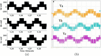
Fig. 2. Line voltage of theVSI in frame (400 V/div–5ms). (a) Simulation. (b) Experiment.


 Fig. 3. Phase voltage of the VSI in frame (400 V/div–5 ms). (a) Simulation. (b) Experiment.


Fig. 4. Grid phase voltage (50 V/div–10 ms) and injected current (1 A/div–10 ms). (a) Simulation. (b) Experiment.


Fig. 5. Inverter phase voltage to be connected to the grid with only filter (50 V/div–10 ms). (a) Simulation. (b) Experiment.


Fig. 6. Harmonic spectrum of (a) injected current; (b) phase voltage


Fig. 7. Grid voltage (50 V/div–25 ms) and injected current (1 A/div–25 ms) under step change in the reactive power injected into grid. (a) Simulation. (b) Experiment.


Fig. 8. VSI response with filter for the grid and capacitor voltage (100 V/div–10 ms) with the injected line current (5 A/div–10 ms). (a) Simulation. (b) Experiment.


Fig. 9. Harmonic spectrum analysis with filter. (a) Injected current harmonic content. (b) Filter capacitor voltage harmonic content.


CONCLUSION:


In this paper, the SEIG-based WECS dynamic model has been derived. The VOC grid connected VSI has been investigated for high performance control operation. The test results showed how the control scheme succeeded in injecting the wind power as active or reactive power in order to compensate the weak grid power state. An filter is inserted between VOC VSI and grid to obtain a clean voltage and current waveform with negligible harmonic content and improve the power quality. Also, this technique achieved unity power factor grid operation (average above 0.975), very fast transient response within a fraction of a second (0.4 s) under different possible conditions (wind speed variation and load variation), and high efficiency due to a reduced number of components (average above 90%) has been achieved. Besides the improvement in the converter efficiency, reduced mechanical and electrical stresses in the generator are expected, which improves the overall system performance. The experimental results obtained from a prototype rated at 250 W showed that the current and voltage THD (2.67%, 0.12%), respectively, for the proposed WECS with filter is less than 5% limit imposed by IEEE-519 standard. All results obtained confirm the effectiveness of the proposed system feasible for small-scale WECSs connected to weak grids.


REFERENCES:

[1] V. Kumar, R. R. Joshi, and R. C. Bansal, “Optimal control of matrix-converter-based WECS for performance enhancement and efficiency optimization,” IEEE Trans. Energy Convers., vol. 24, no. 1, pp. 264–272, Mar. 2009.

[2] Y. Zhou, P. Bauer, J. A. Ferreira, and J. Pierik, “Operation of grid connected DFIG under unbalanced grid voltage,” IEEE Trans. Energy Convers., vol. 24, no. 1, pp. 240–246, Mar. 2009.

[3] S. M. Dehghan, M.Mohamadian, and A. Y. Varjani, “A new variablespeed wind energy conversion system using permanent-magnet synchronous generator and z-source inverter,” IEEE Trans Energy Convers., vol. 24, no. 3, pp. 714–724, Sep. 2009.

[4] K. Tan and S. Islam, “Optimum control strategies for grid-connected wind energy conversion system without mechanical sensors,” WSEAS Trans. Syst. Control, vol. 3, no. 7, pp. 644–653, Jul. 2008, 1991-8763.

[5] B. C. Rabelo, W. Hofmann, J. L. da Silva, R. G. de Oliveira, and S. R. Silva, “Reactive power control design in doubly fed induction generators for wind turbines,” IEEE Trans. Ind. Elect., vol. 56, no. 10, pp. 4154–4162, Oct. 2009.

Design of a PEV Battery Charger with High Power Factor using Half-bridge LLC-SRC Operating at Resonance Frequency

 ABSTRACT:

This paper presents a two stage battery charger for plug-in electric vehicles (PEV) based on half-bridge LLC series resonant converter (SRC) operating at resonance frequency. The first stage is power factor correction (PFC) stage comprising of boost converter topology using hysteresis band control of inductor current. The PFC stage reduces the total harmonic distortion (THD) of the line current for achieving high power factor and regulates the voltage to follow the battery voltage at DC link capacitor. The input of the boost converter is a single phase 50 Hz, 220V AC from grid. At the second stage, a half bridge LLC-SRC is used for constant-current, constant-voltage (CC-CV) based battery charging and for providing galvanic isolation. The resonant converter is designed to operate around resonance frequency to have maximum efficiency and low turnoff current of power switches to reduce switching losses. The circuit is simulated using MATLAB Simulink with 1.5 kW maximum output power. Simulation results show that the PFC stage achieves THD less than 0.07% and high power factor value as 0.9976. The DC/DC stage meets all the CC-CV charging requirements of the battery over wide voltage range 320V—420V for depleted to fully charged battery.

KEYWORDS:

1.      LLC Resonant converter

2.      PEV battery charger

3.      PFC

4.      Hysteresis band control

5.      FHA

SOFTWARE: MATLAB/SIMULINK

BLOCK DIAGRAM:


Fig. 1. Schematic of the proposed battery charger.

EXPECTED SIMULATION RESULTS:


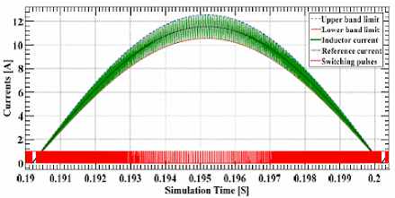
Fig. 2. Boost inductor current for a half cycle of input voltage.


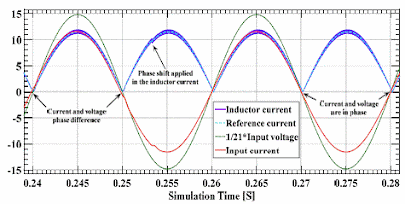
Fig. 3. AC voltage and current after power factor correction.


Fig. 4. LLC-SRC operating at key point A (V0 = 320V, and I0 = 3.57A).


Fig. 5. LLC-SRC operating at key point B (V0 = 360V, and I0 = 3.57A).


Fig. 6. LLC-SRC operating at key point C (V0 = 420V, and I0 = 3.57A).


Fig. 7. LLC-SRC operating at key point D (V0 = 420V, and I0 = 0.25A).


CONCLUSION:

 In this paper, a 1.5 kW PEV battery charger with emphasis on the design of LLC-SRC for DC-DC stage of the battery charger is presented. A method for improvement in the power factor with boost converter is presented using hysteresis current control to keep line input voltage and current in phase using phase shift in inductor current. Simulation results show that the PFC stage achieves minimum THD as 0.07% and a power factor of 0.9976 having line current and voltage in phase. The LLC-SRC is designed to operate around resonance frequency to achieve maximum benefits of LLC converter, having minimum circulating energy, avoiding hard commutation of secondary rectifier diodes. Simulation results for the converter performance are presented which show that the turning off current of power switches have very low value throughout the charging process and is below 2.4A. Hence, the converter have minimum switching and conduction losses.

REFERENCES:

[1] H. Wang, S. Dusmez, and A. Khaligh, "A novel approach to design EV battery chargers using SEPIC PFC stage and optimal operating point tracking technique for LLC converter," Applied Power Electronics Conference and Exposition (APEC), 2014 Twenty-Ninth Annual IEEE, pp.1683-1689, 16-20 March 2014.

[2] H. Wang, S. Dusmez, and A. Khaligh, "Design and Analysis of a Full-Bridge LLCBased PEV Charger Optimized for Wide Battery Voltage Range," Vehicular Technology, IEEE Transactions on, Vol. 63, No. 4, pp.1603-1613, May 2014.

[3] J. Deng, S. Li, S. Hu, C.C. Mi, and R. Ma, "Design Methodology of LLC Resonant Converters for Electric Vehicle Battery Chargers," Vehicular Technology, IEEE Transactions on, Vol. 63, No. 4, pp.1581-1592, May 2014.

[4] Marian K. Kazimierczuk, "Pulse-width Modulated DC-DC Power Converters," Ohio, USA: John Wiley & Sons Ltd, pp. 129-134, 2008.

[5] H. Wang, and A. Khaligh, "Comprehensive Topological Analyses of Isolated Resonant Converters in PEV Battery Charging Applications," Transportation Electrification Conference and Expo (ITEC), 2013 IEEE, pp.1-7, 16-19 June 2013.


Design of a New Combined Cascaded Multilevel Inverter Based on Developed H-Bridge with Reduced Number of IGBTs and DC Voltage Sources

 ABSTRACT:

In this paper, a new combined cascaded multilevel inverter with reduced number of switches and DC voltage sources which is formed by series connection of same units with developed H-Bridge is proposed. For the purpose of generating all even and odd voltage levels 5 algorithms to determine the magnitudes of DC voltage sources is proposed. In order to investigate the advantages and disadvantages of the proposed combined cascaded multilevel inverter the proposed algorithms are compared to presented topologies from different points of view. The experimental results of the proposed topology are stated to check and verifying the performance of the proposed topology.

KEYWORDS:

1.      Multilevel inverter

2.      Cascaded multilevel inverter

3.      Combined topology

4.      Developed H-Bridge

SOFTWARE: MATLAB/SIMULINK

 CIRCUIT DIAGRAM:


Fig. 1. Basic topology of proposed multilevel inverter.

EXPECTED SIMULATION RESULTS:


Fig. 2. Experimental results; (a) output voltage; (b) output voltage and current; (c) generated voltage levels by right side; (d) generated voltage levels by left side; (e) generated voltage levels by L,1 u ; (f) voltage across R2,2 S ; (g) voltage across 1 T ; (h) voltage across 3 T ; (i) voltage across a T .

CONCLUSION:

 In this paper, a new combined cascaded multilevel inverter has been proposed. After that, five different algorithms are proposed in order to determine the magnitudes of the DC voltage sources. By comparing these algorithms, it was concluded that the algorithm which generates a high number of voltage levels with less number of switches and DC voltage sources is better than other algorithms. According to this comparison, it was found that the fifth proposed algorithm is better among the proposed algorithms. In order to prove the claim about reduction of the number of IGBTs and DC voltage sources in the proposed topology, this topology was compared to presented topologies from different aspects. In these comparisons, it was found that the proposed topology generates 31 voltage levels with 14 IGBTs while presented topologies in [4], [10] and [12] generate the same number of voltage levels with 32, 16 and 34 IGBTs, respectively. Also, it was found that this number of voltage levels needs 4 DC voltage sources, whereas, the topologies which presented in [4] and [12] generate 17 and 9 voltage levels with the same number of DC voltage sources. Afterwards, correctness of performance of the proposed topology and relations have been verified through experimentation of the proposed topology with 2 input units in each side.

REFERENCES:

[1] C.I. Odeh, E.S. Obe, and O. Ojo,: “Topology for cascaded multilevel inverter,” IET Power Electron., vol. 9, no. 5, pp. 921-929, April 2016.

[2] E. Zamiri, N. Vosoughi, S.H. Hosseini, R. Barzegarkhoo, and M. Sabahi, “A new cascaded switched-capacitor multilevel inverter based on improved series–parallel conversion with less number of components,” IEEE Trans. Ind. Electron., vol. 63, no. 6, pp. 3582-3594, June 2016.

[3] N. Prabaharan and K. Palanisamy, “Analysis of cascaded H-bridge multilevel inverter configuration with double level circuit,” IET Power Electron., vol. 10, no. 9, pp. 1023-1033, July 2017.

[4] M.R. Banaei, M.R. Jannati Oskuee and H. Khounjahan, “Reconfiguration of semi-cascaded multilevel inverter to improve systems performance parameters,” IET Power Electron., vol. 7, no. 5, pp. 1106-1112, May 2014.

[5] E. Babaei, S. Laali, and Z. Bayat, “A single-phase cascaded multilevel inverter based on a new basic unit with reduced number of power switches,” IEEE Trans. Ind. Electron., vol. 62, no. 2, pp. 922-929, Feb. 2015.