In this paper, a new combined cascaded multilevel inverter
with reduced number of switches and DC voltage sources which is formed by
series connection of same units with developed H-Bridge is proposed. For the
purpose of generating all even and odd voltage levels 5 algorithms to determine
the magnitudes of DC voltage sources is proposed. In order to investigate the
advantages and disadvantages of the proposed combined cascaded multilevel
inverter the proposed algorithms are compared to presented topologies from
different points of view. The experimental results of the proposed topology are
stated to check and verifying the performance of the proposed topology.
KEYWORDS:
1.
Multilevel inverter
2.
Cascaded multilevel inverter
3.
Combined topology
4.
Developed H-Bridge
SOFTWARE: MATLAB/SIMULINK
Fig.
1. Basic topology of proposed multilevel inverter.
EXPECTED SIMULATION RESULTS:
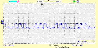
Fig.
2. Experimental results; (a) output voltage; (b) output voltage and current;
(c) generated voltage levels by right side; (d) generated voltage levels by
left side; (e) generated voltage levels by L,1 u ; (f) voltage
across R2,2 S ; (g) voltage across 1 T ; (h) voltage
across 3 T ; (i) voltage across a T .
REFERENCES:
[1]
C.I. Odeh, E.S. Obe, and O. Ojo,: “Topology for cascaded multilevel inverter,” IET
Power Electron., vol. 9, no. 5, pp. 921-929, April 2016.
[2]
E. Zamiri, N. Vosoughi, S.H. Hosseini, R. Barzegarkhoo, and M. Sabahi, “A new
cascaded switched-capacitor multilevel inverter based on improved series–parallel
conversion with less number of components,” IEEE Trans. Ind. Electron., vol.
63, no. 6, pp. 3582-3594, June 2016.
[3]
N. Prabaharan and K. Palanisamy, “Analysis of cascaded H-bridge multilevel
inverter configuration with double level circuit,” IET Power Electron., vol.
10, no. 9, pp. 1023-1033, July 2017.
[4]
M.R. Banaei, M.R. Jannati Oskuee and H. Khounjahan, “Reconfiguration of
semi-cascaded multilevel inverter to improve systems performance parameters,” IET
Power Electron., vol. 7, no. 5, pp. 1106-1112, May 2014.
[5]
E. Babaei, S. Laali, and Z. Bayat, “A single-phase cascaded multilevel inverter
based on a new basic unit with reduced number of power switches,” IEEE
Trans. Ind. Electron., vol. 62, no. 2, pp. 922-929, Feb. 2015.


