ABSTRACT:
A novel switched-capacitor inverter is proposed. The
proposed inverter outputs larger voltage than the input voltage by switching
the capacitors in series and in parallel. The maximum output voltage is
determined by the number of the capacitors. The proposed inverter, which does
not need any inductors, can be smaller than a conventional two-stage unit which
consists of a boost converter and an inverter bridge. Its output harmonics are
reduced compared to a conventional voltage source single phase full bridge
inverter. In this paper, the circuit configuration, the theoretical operation,
the simulation results with MATLAB/ SIMULINK, and the experimental results are
shown. The experimental results accorded with the theoretical calculation and
the simulation results.
1.
Charge pump
2.
Multicarrier
PWM
3.
Multilevel
inverter
4.
Switched
capacitor (SC)
Fig. 1. Circuit topology of the switched-capacitor inverter using series/ parallel conversion.
Fig. 2. Simulated voltage waveforms of the proposed inverter (n = 2) designed for low power at 5.76 [W], switching frequency f = 40 [kHz] and reference waveform frequency fref = 1 [kHz]. (a) Bus voltage waveform vbus and (b) the output voltage waveform vout.
Fig. 3. Simulated voltage waveforms of the proposed inverter (n = 2) designed for high power at 4.50 [kW], switching frequency f = 40 [kHz] and reference waveform frequency fref = 1 [kHz]. (a) Bus voltage waveform vbus and (b) the output voltage waveform vout.
Fig. 4. Simulated current waveforms of the capacitor iC1 in the proposed inverter (n = 2).(a) Designed for low power at 5.76 [W] and (b) designed for high power at 4.50 [kW].
Fig. 5. Simulated spectra of the bus voltage waveform of the proposed inverters (n = 2) normalized with the fundamental component. (a) Designed for low power at 5.76 [W] and (b) designed for high power at 4.50 [kW].
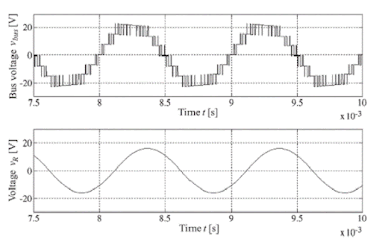
Fig. 6. Simulated bus voltage waveforms vbus and the voltage waveforms of the load resistance vR of the proposed inverter (n = 2) designed for low power at 5.76 [W] with an inductive load.
CONCLUSION:
REFERENCES:
[1]
H. Liu, L. M. Tolbert, S. Khomfoi, B. Ozpineci, and Z. Du, “Hybrid cascaded
multilevel inverter with PWM control method,” in Proc. IEEE Power Electron.
Spec. Conf., Jun. 2008, pp. 162–166.
[2]
A. Emadi, S. S. Williamson, and A. Khaligh, “Power electronics intensive solutions
for advanced electric, hybrid electric, and fuel cell vehicular power systems,”
IEEE Trans. Power Electron., vol. 21, no. 3, pp. 567–577, May 2006.
[3]
L. G. Franquelo, J. Rodriguez, J. I. Leon, S. Kouro, R. Portillo, and M. A. M.
Prats, “The age of multilevel converters arrives,” IEEE Ind. Electron. Mag.,
vol. 2, no. 2, pp. 28–39, Jun. 2008.
[4]
Y. Hinago and H. Koizumi, “A single phase multilevel inverter using switched
series/parallel DC voltage sources,” IEEE Trans. Ind. Electron., vol.
57, no. 8, pp. 2643–2650, Aug. 2010.
[5]
S. Chandrasekaran and L. U. Gokdere, “Integrated magnetics for interleaved
DC–DC boost converter for fuel cell powered vehicles,” in Proc. IEEE Power
Electron. Spec. Conf., Jun. 2004, pp. 356–361.


