ABSTRACT:
A
multi-cell hybrid 21-Level multilevel inverter is proposed in this paper. The
proposed topology includes two-unit; an H-bridge is cascaded with a modified
K-type unit to generate an output voltage waveform with 21 levels based only on
two unequal DC suppliers. The proposed topology's advantage lies in the fine
and clear output voltage waveforms with high output efficiency. Meanwhile, the
high number of output voltage waveform levels generates a low level of
distortion and reduces the level of an electromagnetic interface (EMI).
Moreover, it reduces the voltage stress on the switching devices and gives it a
long lifetime. Also, the reduction in the number of components has a noticeable
role in saving size and cost. Regarding the capacitors charging, the proposed
topology presents an online method for charging and balancing the capacitor's
voltage without any auxiliary circuits. The proposed topology can upgrade to a
high number of output steps through the cascading connection. Undoubtedly this
cascading will increase the power level to medium and high levels and reduce
the harmonics content to a neglectable rate. The proposed system has been
tested through the simulation results, and an experimental prototype based on
the controller dSPACE (DS-1103) hardware unit used to support the simulation
results.
KEYWORDS:
1. 21-Level Multilevel Inverter (MLI)
2. Hybridization
3. Modified K-type inverter
4. Online charging
5. Self-balancing
6. Voltage boosting inverter
7. Total Harmonic Distortion (THD)
SOFTWARE: MATLAB/SIMULINK
Figure.1 Proposed Hybrid MLI Topology
Figure.2 21L MLI output voltage waveform
Figure.3 FFT analysis of the 21L output voltage waveform
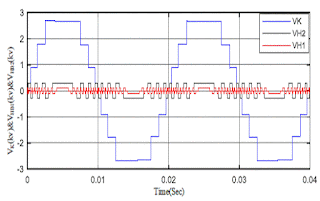
Figure.4 Capacitor voltages and the output voltage waveform
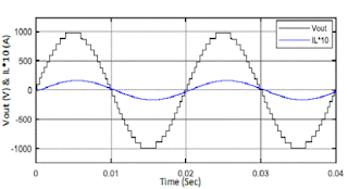
Figure.5 Output voltage and load current waveforms
Figure.6 63L cascaded system output
voltage and load current
Figure.7 FFT analysis of the 63L output voltage waveform
Figure.8 Output voltages of 2HB+K cascaded system units
Figure.9 147L cascaded system output
voltage and load current
Figure.10 FFT analysis of the 147L output voltage waveform
Figure.11 Output voltages of
Asymmetrical cascaded system units
[1] F. Z. Peng, W. Qian, and D. Cao, "Recent advances in multilevel converter/inverter topologies and applications," in The 2010 International Power Electronics Conference-ECCE ASIA-, 2010, pp. 492-501.
[2] J. Rodriguez, J.-S. Lai, and F. Z. Peng, "Multilevel inverters: a survey of topologies, controls, and applications," IEEE Transactions on Industrial Electronics, vol. 49, pp. 724-738, 2002.
[3] L. M. Tolbert and X. Shi, "Multilevel power converters," in Power Electronics Handbook, ed: Elsevier, 2018, pp. 385-416.
[4] K. K. Gupta, A. Ranjan, P. Bhatnagar, L. K. Sahu, and S. Jain, "Multilevel inverter topologies with reduced device count: A review," IEEE transactions on power electronics, vol. 31, pp. 135-151, 2015.
[5]
P. Omer, J. Kumar, and B. S. Surjan, "A Review on Reduced Switch Count
Multilevel Inverter Topologies," IEEE Access, vol. 8, pp.
22281-22302, 2020.


