asokatechnologies@gmail.com 09347143789/09949240245

Search This Blog

Sunday 18 January 2015

24-Pulse Rectifier Realization By 3-Phase To Four 3-Phase Transformation Using Conventional Transformers

24-Pulse Rectifier Realization By 3-Phase To Four 3-Phase
Transformation Using Conventional Transformers


ABSTRACT:

 A 24-pulse rectifier has been designed for high voltage, low current applications. Four 3-phase systems are obtained from a single 3-phase source using novel interconnection of conventional single- and 3-phase transformers. From two 30º displaced 3-phase systems feeding two 6-pulse rectifiers that are series connected, a 12-pulse rectifier topology is obtained. Thus, from the four 3-phase systems that are displaced by 15º two 12-pulse rectifiers are obtained that are cascaded to realize a 24-pulse rectifier. Phase shifts of 15º and 30º are made using phasor addition of relevant line voltages with a combination of single-phase and three-phase transformers respectively. PSCAD based simulation and experimental results that confirm the design efficacy are presented.

 SOFTWARE: MATLAB/SIMULINK

 BLOCK DIAGRAM:

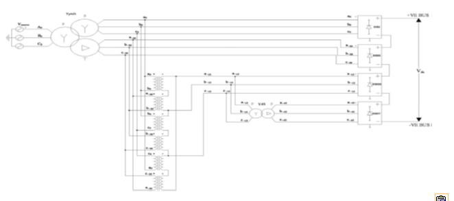
Figure 1 24-pulse rectifier realized by transforming a single 3-phase system to four 3-phase systems using conventional single- and three-phase transformers

EXPECTED SIMULATION RESULTS:


Figure 2 Input line voltages Va0b0, Vb0c0 and Vc0a0 at diode bridge I

Figure 3 Input line voltages Va30b30, Vb30c30 and Vc30a30 at diode bridge II


Figure 4 Input line voltages Va15b15, Vb15c15 and Vc15a15 at diode bridge III

Figure 5 Input line voltages Va45b45, Vb45c45 and Vc45a45 at diode bridge IV

 
Figure 6 Line current in phase a of y0 winding of Yy0d1 main transformer


Figure 7 Line current in phase a of d1 winding of Yy0d1 main transformer


Figure 8 Six-pulse dc output voltage of diode bridge, DBI


Figure 9 DC 6-pulse output voltage of diode bridge, DBII


Figure 10 DC 12-pulse output voltage by cascading diode bridges I and II


Figure 11 Six-pulse dc output voltage of diode bridge, DBIII


Figure 12 DC 6-pulse output voltage of diode bridge, DBIV


Figure 13 DC 12-pulse output voltage by cascading diode bridges III and IV


Figure 14 DC 24-pulse voltage by cascading DBI, DBII, DBIII and DBIV


Figure 15 Line current in phase a of Y winding of Yy0d1 main transformer


Figure 16 Line current in phase a of Y winding of Yy0d1 main transformer


Figure 17 Panned view of 24-pulse dc voltage


 Figure 18 24-pulse dc voltage


 Figure 19 Experimental set up        

CONCLUSION:

A 24-pulse rectifier is realized by conventional transformers that meets the theoretical harmonic
and ripple estimates.

REFERENCES:

 [1] IEEE Recommended Practices and Requirements for Harmonics Control in Electric Power Systems, IEEE Std. 519, 1992.
[2] Electromagnetic Compatibility (EMC)—Part 3: Limits-Section 2: Limits for Harmonic Current Emissions (Equipment Input Current (16A per Phase), IEC1000-3-2, Dec., 1995.
[3] Draft-Revision of Publication IEC 555-2: Harmonics, Equipment for Connection to the Public Low Voltage Supply System, IEC SC 77A, 1990.
[4] Bhim Singh, B. N. Singh, A. Chandra, Kamal Al-Haddad, Ashish Pandey, and D. P. Kothari, “A Review of Three-Phase Improved Power Quality AC-DC Converters”, IEEE Trans. Ind. Electron., vol. 51, No. 3, June 2004, 641-660.
[5] S. Choi, “New pulse multiplication technique based on six pulse thyristor converters for high power applications,” IEEE Trans. Ind. Appl., vol. 38, no. 1, pp. 131–136, Jan./Feb. 2002.


Sunday 4 January 2015

Implementation Of Perturb And Observe MPPT Of PV System with Direct Control Method Using Buck And Buck boost Converters

Implementation Of Perturb And Observe MPPT Of PV System with Direct Control Method Using Buck And Buck boost Converters

ABSTRACT:

The Maximum Power Point Tracking (MPPT) is a technique used in power electronic circuits to extract maximum energy from the Photovoltaic (PV) Systems. In the recent decades, photovoltaic power generation has become more important due its many benefits such as needs a few maintenance and environmental advantages and fuel free. However, there are two major barriers for the use of PV systems, low energy conversion efficiency and high initial cost. To improve the energy efficiency, it is important to work PV system always at its maximum power point. So far, many researches are conducted and many papers were published and suggested different methods for extracting maximum power point. This paper presents in details implementation of Perturb and Observe MPPT using buck and buck-boost Converters. Some results such as current, voltage and output power for each various combination have been recorded. The simulation has been accomplished in software of MATLAB Math works.

KEYWORDS

1.      Maximum Power Point Tracking
2.       Perturb and Observe
3.      DC-DC Converters
4.      Photovoltaic System

SOFTWARE: MATLAB/SIMULINK

BLOCK DIAGRAM:


Figure 1. PV module and dc/ dc converter with MPPT


Figure 2. Block diagram of a PV array connected to the load

EXPECTED SIMULATION RESULTS:


Figure 3. Output current, voltage and power of PV panel (insolation changed from 400 to 200 w/ m² at a time of 4.915 sec.)


Figure 4. Output current, voltage and power of buck converter with P&O algorithm
(Insolation changed from 400 to 200 w/ m² at a time of 4.915 sec.)


Figure 5. output current, voltage and power of PV panel (Insolation changed from 400 to 200 w/ m² at a time of 5.017 sec.)
                                       

Figure 6. Output current, voltage and power of buck-boost converter with P&O algorithm
(Insolation changed from 400 to 200 w/ m² at a time of 5.017 sec.)

CONCLUSION:

P&O MPPT method is implemented with MATLAB-SIMULINK for simulation. The MPPT method simulated in this paper is able to improve the dynamic and steady state performance of the PV system simultaneously. Through simulation it is observed that the system completes the maximum power point tracking successfully despite of fluctuations. When the external environment changes suddenly the system can track the maximum power point quickly. Both buck and buck-boost converters have succeeded to track the MPP but, buck converter is much more effective specially in suppressing the oscillations produced due the use of P&O technique.

REFERENCES:

[1] A.P.Yadav, S. Thirumaliah and G. Harith. “Comparison of MPPT Algorithms for DC-DC Converters Based PV Systems” International Journal of Advanced Research in Electrical, Electronics and Instrumentation Engineering Vol. 1, Issue 1, July 2012.
[2] Y.-H.Chang and C.-Y. Chang, "A Maximum Power Point Tracking of PV System by Scaling Fuzzy Control," presented at International Multi Conference of Engineers and Computer Scientists, Hong Kong, 2010.
[3] S.Mekhilef, "Performance of grid connected inverter with maximum power point tracker and power factor control," International Journal of Power Electronics, vol.1, pp. 49-62.
[4] M.E.Ahmad and S.Mekhilef, "Design and Implementation of a Multi Level Three-Phase Inverter with Less Switches and Low Output Voltage Distortion," Journal of Power Electronics, vol. 9, pp. 594- 604, 2009.

[5] H.N.Zainudin and S. Mekhilef, "Comparison Study of Maximum Power Point Tracker Techniques for PV Systems" Proceedings of the 14th International Middle East Power Systems Conference (MEPCON’10), Cairo University, Egypt, December 19-21, 2010.

Simulation and Analysis of Perturb and Observe MPPT Algorithm for PV Array Using ĊUK Converter

Simulation and Analysis of Perturb and Observe MPPT
Algorithm for PV Array Using ĊUK Converter


ABSTRACT:

This paper presents the comparative analysis between constant duty cycle and Perturb & Observe (P&O) algorithm for extracting the power from Photovoltaic Array (PVA). Because of nonlinear characteristics of PV cell, the maximum power can be extract under particular voltage condition. Therefore, Maximum Power Point Tracking (MPPT) algorithms are used in PVA to maximize the output power. In this paper the MPPT algorithm is implemented using Ćuk converter. The dynamics of PVA is simulated at different solar irradiance and cell temperature. The P&O MPPT technique is a direct control method enables ease to implement and less complexity.

KEYWORDS

1.      Photovoltaic Array (PVA)
2.       MPPT
3.       ĆUK Converter

SOFTWARE: MATLAB/SIMULINK

BLOCK DIAGRAM:


Fig. 1: Block Diagram of MPPT Using PI Controller


Fig. 2: Block Diagram of Direct Duty Cycle (δ) Control MPPT

EXPECTED SIMULATION RESULTS:


Fig. 3: MATLAB/SIMULINK Model of PVCC for δ =0.6


Fig. 4: Output Power Curve of the PV Module and Ćuk Converter for Constant δ = 0.6 and Different β.


Fig. 5: Output Power Curve of the PV Module and Ćuk Converter for Constant δ = 0.6 and Different T


Fig. 6: MATLAB/SIMULINK Model of PVCC Using P & O Algorithm


Fig. 7: Output Power Curve of the PV Module and Ćuk Converter for Different β and P&O MPPT


Fig. 8: Output Power Curve of the PV Module and Ćuk Converter for Different T and P & O MPPT.

CONCLUSION:

In this paper, P&O and constant duty cycle algorithm of MPPT is implemented using ĆUK converter. The model is simulated with MATLAB/SIMULINK. It is shown that PV system output power increases with rise in solar irradiance and fall in cell temperature. Therefore, solar cell performance better in winter season than summer. The P&O gives the optimum duty cycle as compare to Constant duty cycle control, to extract the maximum power from PV system.

REFERENCES:

[1] Ali Chermitti, Omar Boukli-Hacene and Samir Mouhadjer (2012) “Design of a Library of Components for Autonomous Photovoltaic System under Matlab/Simulink”, International Journal of Computer Applications (0975 – 8887), Volume 53– No.14.
[2] Ankur Bhattacharjee (2012) “Design and Comparative Study of Three Photovoltaic Battery Charge Control Algorithms in MATLAB/SIMULINK Environment”, International Journal of Advanced Computer Research (ISSN (print): 2249-7277 ISSN (online): 2277-7970), Volume-2 Number-3 Issue-5.
[3] Athimulam Kalirasu and Subharensu Sekar Dash (2010) “Simulation of Closed Loop Controlled Boost Converter for Solar Installation,” SERBIAN JOURNAL OF ELECTRICAL ENGINEERING, Vol. 7, No. 1.
[4] Azadeh Safari and Saad Mekhilef (2011) “Simulation and Hardware Implementation of Incremental Conductance MPPT with Direct Control Method Using Cuk Converter”, IEEE Transaction on Industrial Electronics, Vol.58, no.4.

[5] E. Durán, M.B. Ferrera, J.M. Andújar, M.S. Mesa (2011) “I-V and P-V Curves Measuring System for PV Modules based on DC-DC Converters and Portable Graphical Environment” IEEE, 978-1-4244.

Sunday 28 December 2014

Transformer less Inverter with Virtual DC Bus Concept for Cost-Effective Grid-Connected PV Power Systems

Transformer less Inverter with Virtual DC Bus Concept for Cost-Effective Grid-Connected PV Power Systems

ABSTRACT:

In order to eliminate the common-mode (CM) leakage current in the transformer less photovoltaic (PV) systems, the concept of the virtual dc bus is proposed in this paper. By connecting the grid neutral line directly to the negative pole of the dc bus, the stray capacitance between the PV panels and the ground is bypassed. As a result, the CM ground leakage current can be suppressed completely. Meanwhile, the virtual dc bus is created to provide the negative voltage level for the negative ac grid current generation. Consequently, the required dc bus voltage is still the same as that of the full-bridge inverter. Based on this concept, a novel transformer less inverter topology is derived, in which the virtual dc bus is realized with the switched capacitor technology. It consists of only five power switches, two capacitors, and a single filter inductor. Therefore, the power electronics cost can be curtailed. This advanced topology can be modulated with the uni polar sinusoidal pulse width modulation (SPWM) and the double frequency SPWM to reduce the output current ripple. As a result, a smaller filter inductor can be used to reduce the size and magnetic losses. The advantageous circuit performances of the proposed transformer less topology are analyzed in detail, with the results verified by a 500-W prototype.


KEYWORDS

1.      Common mode (CM) current
2.       Photovoltaic (PV) system
3.       Switched capacitor
4.       Transformer less inverter
5.       Unipolar sinusoidal pulse width modulation (SPWM)
6.       Virtual dc bus.

SOFTWARE: MATLAB/SIMULINK

BLOCK DIAGRAM:

Fig.1. Proposed topology.

 EXPECTED SIMULATION RESULTS:


Fig.2. Output current and grid voltage.


Fig.3. Current harmonics distribution.


Fig.4. Simulation waveform for reactive power generation


Fig.5. Current stress on S3 .


Fig. 6. Enlarged figure for current stress on S3

.                                     


 Fig. 7. CM current of H5 circuit.


Fig. 8. Current stress under different capacitor ratios for the proposed circuit: (a) C1 /C2 = 1/2; (b) C1 /C2 = 2/1.
             
CONCLUSION:

The concept of the virtual dc bus is proposed to solve the CM current problem for the transformer less grid-connected PV inverter. By connecting the negative pole of the dc bus directly to the grid neutral line, the voltage on the stray PV capacitor is clamped to zero. This eliminates the CM current completely. Meanwhile, a virtual dc bus is created to provide the negative voltage level. The required dc voltage is only half of the half bridge solution, while the performance in eliminating the CM current is better than the full-bridge-based inverters. Based on this idea, a novel inverter topology is proposed with the virtual dc bus concept by adopting the switched capacitor technology. It consists of only five power switches and a single filter inductor. The proposed topology is especially suitable for the small-power single-phase applications, where the output current is relatively small so that the extra current stress caused by the switched capacitor does not cause serious reliability problem for the power devices and capacitors. With excellent performance in eliminating the CM current, the virtual dc bus concept provides a promising solution for the transformer less grid-connected PV inverters.

REFERENCES:

[1] J. P. Benner and L. Kazmerski, “Photovoltaics gaining greater visibility,” IEEE Spectr., vol. 36, no. 9, pp. 34–42, Sep. 1999.
[2] Z. Zhao, M. Xu, Q. Chen, J.-S. Lai, and Y. Cho, “Derivation of boost-buck converter based high-efficiency robust PV inverter,” in Proc. IEEE Energy Convers. Cong. Expos., Sep. 12–16, 2010, pp. 1479–1484.
[3] R.W. Erickson and A. P. Rogers, “A microinverter for building-integrated photovoltaics,” in Proc. 24th Annu. IEEE Appl. Power Electron. Conf. Expos., Feb. 15–19, 2009, pp. 911–917.
[4] S. B. Kjaer, J. K. Pedersen, and F. Blaabjerg, “A review of single-phase grid-connected inverters for photovoltaic modules,” IEEE Trans. Ind. Appl., vol. 41, no. 5, pp. 1292–1306, Sep./Oct. 2005.

[5] E. Koutroulis and F. Blaabjerg, “Design optimization of grid-connected PV inverters,” in Proc. 26th Annu. IEEE Appl. Power Electron. Conf. Expos., Mar. 6–11, 2011, pp. 691–698.