24-Pulse Rectifier Realization By 3-Phase To Four 3-Phase
Transformation Using Conventional Transformers
ABSTRACT:
A 24-pulse rectifier has been designed for high
voltage, low current applications. Four 3-phase systems are obtained from a
single 3-phase source using novel interconnection of conventional single- and 3-phase
transformers. From two 30º displaced 3-phase systems feeding two 6-pulse
rectifiers that are series connected, a 12-pulse rectifier topology is
obtained. Thus, from the four 3-phase systems that are displaced by 15º two
12-pulse rectifiers are obtained that are cascaded to realize a 24-pulse
rectifier. Phase shifts of 15º and 30º are made using phasor addition of
relevant line voltages with a combination of single-phase and three-phase
transformers respectively. PSCAD based simulation and experimental results that
confirm the design efficacy are presented.
SOFTWARE: MATLAB/SIMULINK
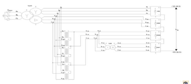
BLOCK DIAGRAM:
Figure 1 24-pulse rectifier realized by transforming
a single 3-phase system to four 3-phase systems using conventional single- and
three-phase transformers
EXPECTED SIMULATION RESULTS:
Figure 2 Input line voltages Va0b0, Vb0c0 and Vc0a0 at
diode bridge I
Figure 3 Input line voltages Va30b30, Vb30c30 and Vc30a30
at diode bridge II
Figure 4 Input line voltages Va15b15, Vb15c15 and Vc15a15
at diode bridge III
Figure 5 Input line voltages Va45b45, Vb45c45 and Vc45a45
at diode bridge IV
Figure 6 Line current in phase a of y0 winding of
Yy0d1 main transformer
Figure 7 Line current in phase a of d1 winding of
Yy0d1 main transformer
Figure 8 Six-pulse dc output voltage of diode bridge,
DBI
Figure 9 DC 6-pulse output voltage of diode bridge,
DBII
Figure 10 DC 12-pulse output voltage by cascading
diode bridges I and II
Figure 11 Six-pulse dc output voltage of diode
bridge, DBIII
Figure 12 DC 6-pulse output voltage of diode bridge,
DBIV
Figure 13 DC 12-pulse output voltage by cascading
diode bridges III and IV
Figure 14 DC 24-pulse voltage by cascading DBI,
DBII, DBIII and DBIV
Figure 15 Line current in phase a of Y winding of
Yy0d1 main transformer
Figure 16 Line current in phase a of Y winding of
Yy0d1 main transformer
Figure 17 Panned view of 24-pulse dc voltage
Figure 18 24-pulse dc voltage
Figure 19 Experimental set up
CONCLUSION:
A
24-pulse rectifier is realized by conventional transformers that meets the
theoretical harmonic
and
ripple estimates.
REFERENCES:
[1] IEEE Recommended Practices and
Requirements for Harmonics Control in Electric Power Systems, IEEE Std. 519, 1992.
[2]
Electromagnetic Compatibility (EMC)—Part 3: Limits-Section 2: Limits for
Harmonic Current Emissions (Equipment Input Current (16A per Phase),
IEC1000-3-2, Dec., 1995.
[3]
Draft-Revision of Publication IEC 555-2: Harmonics, Equipment for Connection to
the Public Low Voltage Supply System, IEC SC 77A, 1990.
[4]
Bhim Singh, B. N. Singh, A. Chandra, Kamal Al-Haddad, Ashish Pandey, and D. P.
Kothari, “A Review of Three-Phase Improved Power Quality AC-DC Converters”,
IEEE Trans. Ind. Electron., vol. 51, No. 3, June 2004, 641-660.
[5]
S. Choi, “New pulse multiplication technique based on six pulse thyristor
converters for high power applications,” IEEE Trans. Ind. Appl., vol.
38, no. 1, pp. 131–136, Jan./Feb. 2002.


