ABSTRACT:
To design a control system it is desirable to
represent the actual system in mathematical form. So a mathematical representation
of a permanent magnet synchronous motor is presented here. The inductances of a
PMSM vary as a function of rotor position, the d-q model is commonly used to
represent PMSM. The d-q model is obtained to implement the current control in
rotor reference frame. A fuzzy logic based speed controller for permanent
magnet synchronous motor is proposed and investigated. In the paper the dynamic
response of PMSM drive with proposed controller is analyzed for different
loading conditions and with various speed.
KEYWORDS:
1.
FLC
2.
Mathematical model
3.
PI controller
4.
PMSM
5.
SVM
SOFTWARE: MATLAB/SIMULINK
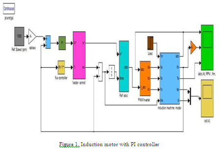
BLOCK DIAGRAM:

EXPECTED SIMULATION RESULTS:


CONCLUSION:
A
mathematical modeling of PMSM is presented here and d-q model is obtained to
implement the current control in rotor reference frame. In this paper
performance of a FLC is investigated to speed control of PMSM. FLC is designed
with three scaling factors (two inputs & one output) for setting the controller
parameter according to actual system. Tuning of these scaling factors is done
based on the parameter of motor and intervals for which membership functions
are defined. Performance of proposed FLC with gain tuning is found good in all
operating conditions.
REFERENCES:
[1] M. Kadjoudj, M. E. H. Benbouzid, C.
Ghennai, and D. Diallo, "A robust hybrid current control for permanent-magnet
synchronous motor drive," IEEE Transactions on Energy
Conversion, vol. 19, pp. 109- 115, 2004.
[2]
Y. Baudon, D. Jouve, and J. P. Ferrieux, "Current control of permanent
magnet synchronous machines. Experimental and simulation study," IEEE
Transactions on Power Electronics, vol. 7, pp. 560- 567, 1992.
[3]
B. K. Bose, Modern power electronics and AC drives: Prentice Hall PTR
USA, 2002.
[4]
R. H. Park, "Two-reaction theory of synchronous machines-II," Transactions
of theAmerican Institute of Electrical Engineers, vol. 52, pp.
352-354, 1933.
[5]
P. Vas, Sensorless vector and direct torque control vol. 729: Oxford
university press Oxford, UK, 1998.