asokatechnologies@gmail.com 09347143789/09949240245

Search This Blog

Friday 27 November 2015

Modeling and Simulation of Micro-grid Based on Small-hydro


ABSTRACT:

As a renewable resource, small hydro is gaining more and more attention due to its variable advantages. The paper focuses on the operation of the micro-grid based on small-hydro. A simulation model of the micro-grid is established by Simulink, which takes the following two cases into account, the grid-connected operation and isolated operation. Under these two cases, the differences of the excitation voltage and rotator speed are analyzed respectively. Power quality of the voltage is also analyzed. Faults are pre-set in the grid and micro-grid. Then the operations of the micro-grid when faults happen are simulated. By comparison of the results, the effects of the fault-cutting-off time are discussed.

KEYWORDS:

1.      Small-hydro
2.       Micro-grid
3.       Model
4.       Simulation
5.      Faults

SOFTWARE: MATLAB/SIMULINK

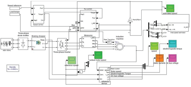
 SIMULING BLOCK DIAGRAM:


 Fig. 1. Simulation model of the entire system


EXPECTED SIMULATION RESULTS:
             

  Fig. 2. Field voltage of generator
             
                                            
    Fig. 3. Rotator speed of generator
 
                                
    Fig. 4. Output voltage (RMS) of generator 1(THD=0.80%)


      Fig. 5. Active power assumption of load 1
                                    
                                
         Fig. 6. Field voltage of generator


 Fig. 7. Rotator speed of generator


  Fig. 8. Output voltage (RMS) of generator 1(THD=1.91%) 


   Fig. 9. Active power assumption of load 1
        
       Fig. 10. Field voltage of generator
         
 Fig. 11. Rotator speed of generator
              
    Fig. 12. Output voltage (RMS) of generator 1
 
         
Fig. 13. Active power assumption of load 1


  Fig. 14. Field voltage of generator     

         Fig. 15. Rotator speed of generator
 
    
       Fig. 16. Output voltage (RMS) of generator 1


Fig. 17. Active power assumption of load 1
          
   Fig. 18. Field voltage of generator
                                    
                                  
Fig. 19. Rotator speed of generator


  Fig. 20. Output voltage (RMS) of generator 1
                                  
 
Fig. 21. Active power assumption of load 1

CONCLUSION:
The micro-grid based on small-hydro can work normally without disturbance by simulating the grid-connected operation and islanded operation. The power quality would have been improved when the micro-grid connected to the grid by comparing the waveforms of output voltage and active power assumption. And the THD would have decreased when the micro grid is in grid-connected operation. Analyze the recovering time and influence of fault-cutting time by setting fault to the micro-grid and grid. The simulation results stress the importance of fault-cutting time. Cutting off the fault in time would suppress the system oscillation, and the generators are easier to get synchronous again. The system would oscillate fiercely with high frequency if the fault could not be cut off in time. However, the actual situation is more complex. Considering the change of load, actual situation of small-hydro power plants (changes of water level and so on), development of different distributing power and so on, the structure of the conventional micro-grid will become more complex, so the model in the paper needs some improvement.
 REFERENCES:
[1] Tao YU,Haihua LIANG. “Smart power generation control for microgrids islanded operation based on reinforcement leaning”,. Master's degree thesis of south china university of technoiogy,2012
[2] Fred H. Schwartz, Mohammad Shahidehpour. “Small Hydro As Green Power.” Power Engineering Society General Meeting, USA, 2005, pp. 2050 - 2057.
[3] ZHANG YuanSheng, et al. “The effects on the load model of the distributed network with small hydro power.” 2011 The International Conference on Advanced Power System Automation and Protection, China, 2011, pp.911-916.
[4] Anuradha Wijesinghe, Loi Lei. “Small Hydro Power Plant Analysis and Development,” Electric Utility Deregulation and Restructuring and Power Technologies (DRPT), China, 2011, pp.25 –30.

[5] Guillermo C. Zu˜niga-Neria, Fernando Ornelas-Tellez,J. Jesus Rico. “Optimal Operation of Energy Resources in a Micro-grid.” Power Systems Conference, USA, 2014, pp. 1-6.

Tuesday 24 November 2015

A Modified SEPIC Converter with High Static Gain for Renewable Applications


ABSTRACT:
Two high static gain step-up dc–dc converters based on the modified SEPIC converter are presented in this paper. The proposed topologies present low switch voltage and high efficiency for low input voltage and high output voltage applications. The configurations with magnetic coupling and without magnetic coupling are presented and analyzed. The magnetic coupling allows the increase of the static gain maintaining a reduced switch voltage. The theoretical analysis and experimental results show that both structures are suitable for high static gain applications as a renewable power sources with low dc output voltage. Two experimental prototypes were developed with an input voltage equal to 15 V and an output power equal to 100 W. The efficiency at nominal power obtained with the prototype without magnetic coupling was equal to 91.9% with an output voltage of 150 V. The prototype with magnetic coupling operating with an output voltage equal to 300 V, presents an efficiency at nominal power equal to 92.2%.

KEYWORDS:
1.      DC–DC power conversion
2.       Voltage multiplier and solar power generation

SOFTWARE: MATLAB/SIMULINK

 BLOCK DIAGRAM:
  CIRCUIT DIAGRAM:
 EXPECTED SIMULATION RESULTS:


CONCLUSION:
Two new topologies of non isolated high static gain converters are presented in this paper. The first topology without magnetic coupling can operate with a static gain higher than 10 with a reduced switch voltage. The structure with magnetic coupling can operate with static gain higher than 20 maintaining low the switch voltage. The efficiency of proposed converter without magnetic coupling is equal to 91.9% operating with input voltage equal to 15 V, output voltage equal 150 V, and output power equal 100 W. The efficiency of the proposed converter with magnetic coupling is equal to 92.2% operating with input voltage equal to 15V, output voltage equal 300V, and output power equal 100W. The commutation losses of the proposed converter with magnetic coupling are reduced due to the presence of the transformer leakage inductance and the secondary voltage multiplier that operates as a nondissipative clamping circuit to the output diode voltage.

REFERENCES:
 [1] C. W. Li and X. He, “Review of non-isolated high step-up DC/DC converters in photovoltaic grid-connected applications,” IEEE Trans. Ind. Electron., vol. 58, no. 4, pp. 1239–1250, Apr. 2011.
[2] C. S. B. Kjaer, J. K. Pedersen, and F. Blaabjerg, “A review of singlephase grid-connected inverters for photovoltaic modules,” IEEE Trans. Ind. Appl., vol. 41, no. 5, pp. 1292–1306, Sep. 2005.
[3] D. Meneses, F. Blaabjerg, O. Garcia, and J. A. Cobos, “Review and comparison of step-up transformerless topologies for photovoltaic AC-Module application,” IEEE Trans. Power Electron., vol. 28, no. 6, pp. 2649–2663, Jun. 2013.
[4] D. Zhou, A. Pietkiewicz, and S. Cuk, “A Three-Switch high-voltage converter,” IEEE Trans. Power Electron., vol. 14, no. 1, pp. 177–183, Jan. 1999.
[5] M. Prudente, L. L. Pfitscher, G. Emmendoerfer, E. F. Romaneli, and R. Gules, “Voltage multiplier cells applied to non-isolated DC–DC converters,” IEEE Trans. Power Electron., vol. 23, no. 2, pp. 871–887, Mar. 2008.

Thursday 5 November 2015

Sensorless Speed Estimation and Vector control of an Induction Motor drive Using Model Reference Adaptive Control

ABSTRACT:

Now-a-days, sensorless speed control modes of operation are becoming standard solutions in the area of electric drives. The technological developments require a compact and efficient drive to meet the challenging strategies in operation of the system. This paper provides a speed sensorless control of an Induction motor with a model based adaptive controller with stator current vectors. The purpose of the proposed control scheme is to create an algorithm that will make it possible to control induction motors without sensors. A closed loop estimation of the system with robustness against parameter variation is used for the control approach. A Model Reference Adaptive System (MRAS) is one of the major approaches used for adaptive control. The MRAS provides relatively easy implementation with a higher speed adaptation algorithm. MRAS proposed in this paper owing to its low complexity and less computational effort proposes a feasible methodology to control the speed of an Induction Motor (1M) drive without using speed sensors. Simulations results validate the effectiveness of this technique.

KEYWORDS:
1.      Indirect Field oriented control
2.      Induction motor drive
3.      Sensorless speed estimation

4.      Model Reference Adaptive control.

SOFTWARE: MATLAB/SIMULINK

BLOCK DIAGRAM:

Fig.1. Proposed Block Diagram of MRAS based 1M drive using PI controller.


 SIMULINK MODEL:

Fig.2. Overall Simulink model of sensorless control of induction motor using MRAS with PI controller.


EXPECTED SIMULATION RESULTS:


CONCLUSION:
The model based control scheme is basically an adaptive control mechanism. The reference model of the proposed system consists of the response to be obtained for the input conditions. The adaptive mechanism continuously monitors the adaptable parameter (speed in this case). The
adaptable parameter is continuously subjected to changes based on its deviation obtained by comparing it with the response of the reference model. The speed estimation algorithm in MRAS is computationally less intensive. MRAS is a relatively simple algorithm and hence less sophisticated processing can be employed. MRAS strategy is more robust than the conventional one. This makes it better suited if the drive is to be operated in hostile environments. Owing to less sophisticated processing requirements, MRAS technique costs cheaper and hence overall cost of the drive is reduced. With lower cost and greater reliability without mounting problems, the sensorless vector control schemes have made remarkable developments in electric drive technology. Due to lesser rise time taken by MRAS, this method gives faster steady state response and this scheme has better reliability than the conventional scheme.

REFERENCES:
[I] Teresa Orlowska - Kowalska and Mateusz Dybkowski , "Stator Current based MRAS estimator for a wide range speed Sensor less induction motor drives", IEEE Transactions on Industrial Electronics vo1.51, No. 4, April 2010, pp. 1296 - 1308.
[2] B. K. Bose, Power Electronics and Motor Drives, Pearson Education Inc., Delhi, India, 2003.
[3] M. Rodic and K. Jezernik, "Speed-sensorless sliding-mode torque control of induction motor," IEEE Transactions on Industrial Electronics, vol. 49, no. I, pp. 87-95, February 2002.
[4] L. Harnefors, M. Jansson, R. Ottersten and K. Pietilainen, "Unified sensorless vector control of synchronous and induction motors," IEEE Transactions on Industrial Electronics, vol. 50, no.
1, pp. 153-160, February 2003.
[5] M. Comanescu and L. Xu, "An improved flux observer based on PLL frequency estimator for sensorless vector control of induction motors," IEEE Transactions on Industrial Electronics, vol. 53, no. 1, pp. 50-56, February 2006.


Tuesday 4 August 2015

Power Quality Improvement of Unbalanced Power System with Distributed Generation Units

Power Quality Improvement of Unbalanced Power System with
Distributed Generation Units

ABSTRACT:

This paper presents a power electronic system for improving the power quality of the unbalanced distributed generation units in three-phase four-wire system. In the system, small renewable power generation units, such as small PV generator, small wind turbines may be configured as single phase generation units. The random nature of renewable power sources may result in significant unbalance in the power network and affect the power quality. An electronic converter system is proposed to correct the system unbalance and harmonics so as to deal with the power quality problems. The operation and control of the converter are described. Simulation results have demonstrated that the system can effectively correct the unbalance and enhance the system power quality.

KEYWORDS:

1.      Component
2.      Distributed generation
3.      Voltage source converter
4.      Power Quality Compensator

SOFTWARE: MATLAB/SIMULINK

BLOCK DIAGRAM:


Fig.1. Instantaneous power relationship in a system and a parallel connected compensator with energy storage system


Fig.2.The connection of VSC in a three-phase four-wire system

EXPECTED SIMULATION RESULTS:


Fig.3. Feeder 1 currents and power

 
Fig.4. Feeder 2 currents and power


Fig.5. Grid currents and power


Fig.6. Compensator currents and power

                     
Fig.7. Grid current fundamental component

CONCLUSION:

This paper presents a study of using a voltage source converter (VSC) based compensator to deal with the unbalance and harmonic distortion issue in the low voltage system with embedded single phase DG units. The VSC performs the functions of an interface for an energy storage system as well. The VSC is connected in parallel with the system to control the energy storage system, correct the system unbalance, remove the harmonic components and minimize the neutral current of the supply system.

REFERENCES:

[1] G..Strbac, Impact of dispersed generation on distribution systems: a European perspective” Power Engineering Society Winter Meeting, 2002. IEEE, vol. 1, . 2002, pp. 118 –120.
[2] M. Dussart, P. Lauwers, S. Magnus, Y. Laperches, “Connection requirements for dispersed generation: evolutions of existing requirements and need for further standardizationElectricity Distribution, 2001. Part 1: Contributions. CIRED2001, Conference Publication No. 482, © IEE2001
[3] J.A.P. Lopes, “Integration of dispersed generation on distribution networks-impact studies” Power Engineering Society Winter Meeting, 2002. IEEE, vol. 1, 2002, pp. 323 –328.
[4] F. Blaabjerg, Z. Chen, S. B Kjaer, “Power Electronics as Efficient Interface in Dispersed Power Generation Systems”, IEEE Transactions on Power Electronics, vol. 19, Issue: 5, Sept. 2004, pp.1184- 1194.

[5] Z. Chen, “Three Phase Four Wire System Power Redistribution Using A Power Electronic Converter”, Power Engineering Letters, IEEE Power Eng. Rev. October, 2000, pp. 47-49.

Saturday 1 August 2015

Transient Stability Enhancement by DSSC with Fuzzy Supplementary Controller

Transient Stability Enhancement by DSSC with
Fuzzy Supplementary Controller

ABSTRACT

 The distributed flexible alternative current transmission system (D-FACTS) is a recently developed FACTS technology. Distributed Static Series Compensator (DSSC) is one example of DFACTS devices. DSSC functions in the same way as a Static Synchronous Series Compensator (SSSC), but is smaller in size, lower in price, and possesses more capabilities. Likewise, DSSC lies in transmission lines in a distributed manner. In this work, we designed a fuzzy logic controller to use the DSSC for enhancing transient stability in a two-machine, two-area power system. The parameters of the fuzzy logic controller are varied widely by a suitable choice of membership function and parameters in the rule base. Simulation results demonstrate the effectiveness of the fuzzy controller for transient stability enhancement by DSSC.

KEYWORDS

1.      D-FACTS
2.       Simulation model
3.       DSSC
4.       Transient stability Fuzzy logic controller

SOFTWARE: MATLAB/SIMULINK

 BLOCK DIAGRAM:

Fig. 1. Simulation model of two-machine system for transient stability study with DSSC.


Fig. 2. D-FACTS deployed on the power line.

Fig. 3. Circuit schematic of a DSSC module.


EXPECTED SIMULATION RESULTS:


Fig. 4. Changing the rotor angle difference (d_theta1_2) when the DSSCs entered the circuit.

             
Fig. 5. Changing the rotor angle difference (d_theta1_2) after the fault with DSSC (without supplementary fuzzy logic damping controller) and without DSSC.

 Fig. 6. Changing the angular speed of the machines after the fault with DSSC (without supplementary fuzzy logic damping controller) and without DSSC.


Fig.7. Rotor angle difference (d_theta1_2) deviation after the fault with FLC and classic controller.


Fig. 8. Machine voltage variation after the fault with FLC and classic controller.


Fig. 9. Rotor angle difference (d_theta1_2) deviation after the fault with FLC and classic damping controller and without damping controller.

Fig. 10. Machine voltage variation after the fault with FLC and classic damping controller and without damping controller.

Fig. 11. Variation of FLC output signal after the fault.


CONCLUSION:

In this study, we introduced a graphical-based simulation model of the DSSC. DSSC was placed in a sample two machine power system to increase transient stability. Simulation studies presented in the paper showed that when the DSSCs were out of service, the rotor angle between the machines (d_theta1_2) increased rapidly and two machines fell out of synchronism after fault clearing. However, when the DSSCs were in circuit, DSSCs stabilized the system even without specific controller. Subsequently, an FLC was added to the main control system of the DSSC in order to improve the transient stability margin of the system. The simulation results show that specific to this case, DSSC can stabilize the system under severe fault. Moreover, a comparative study between the FLC and conventional classic controller shows that the proposed FLC has better performance and influence in transient stability enhancement and oscillation damping


REFERENCES:

[1] Yi Guo, David J. Hil and Youyi Wang, “Global Transient Stability and Voltage Regulation for Power System,” IEEE Transaction On Power System, Vol. 16, No. 4, Nov. 2001.
[2] L. Gyugyi, “Dynamic compensation of ac transmission lines by solid-state synchronous voltage sources,” IEEE Trans. Power Delivery, 19(2), 1994, pp.904-911.
[3] P. Rao, M.L. Crow and Z.Young, “STATCOM control for power system voltage control application,” IEEE Trans. Power Delivery, 15, 2000, pp.1311-1317.
[4] H. Wang and F.Li, “Multivariable sampled regulators for the coordinated control of STATCOM ac and dc voltage,” IEE Proc. Gen. Tran. Dist., 147(2), 2000, pp. 93-98.

[5] A.H.M.A Rahim and M.F.Kandlawala, “Robust STATCOM voltage controller design using loop shaping technique,” Electric Power System Research, 68, 2004, pp.61-74.