asokatechnologies@gmail.com 09347143789/09949240245

Search This Blog

Friday 27 November 2015

TS-Fuzzy-Controlled Active Power Filter for Load Compensation


ABSTRACT:
This paper describes the application of Takagi–Sugeno (TS)-type fuzzy logic controller to a three-phase shunt active power filter for the power-quality improvement and reactive power compensation required by a nonlinear load. The advantage of fuzzy logic control is that it does not require a mathematical model of the system. The application of the Mamdani-type fuzzy logic controller to a three-phase shunt active power filter was investigated earlier but it has the limitation of a larger number of fuzzy sets and rules. Therefore, it needs to optimize a large number of coefficients, which increases the complexity of the controller. On the other hand, TS fuzzy controllers are quite general in that they use arbitrary input fuzzy sets, any type of fuzzy logic, and the general defuzzifier. Moreover, the TS fuzzy controller could be designed by using a lower number of rules and classes. Further, in this paper, the hysteresis current control mode of operation is implemented for pulsewidth-modulation switching signal generation. Computer simulation results show that the dynamic behavior of the TS fuzzy controller is better than the conventional proportional-integral (PI) controller and is found to be more robust to changes in load and other system parameters compared to the conventional PI controller.

KEYWORDS:

1.      Dynamic behavior of the controller
2.       Power quality improvement
3.       Shunt active power filter
4.       Takagi–Sugeno (TS) fuzzy logic controller

SOFTWARE: MATLAB/SIMULINK

BLOCK DIAGRAM:


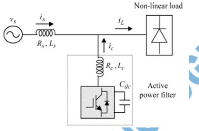
 Fig. 1. Basic compensation principle of APF.

EXPECTED SIMULATION RESULTS:


Fig. 2. Source voltage
                                      

Fig. 3. Source current when the compensator is not connected.


Fig. 4. Source current: PI controller.
                                               

Fig. 5. Source current: TS fuzzy controller


Fig. 6. Load current.


Fig. 7. DC capacitor voltage: load is increased at 0.3 s.


Fig. 8. Source current: PI controller.


Fig. 9. Source currents: TS fuzzy controller
                                                   

Fig. 10. Load current.


Fig. 11. DC capacitor voltage: load is reduced at 0.3 s.


Fig. 12. Source current: PI controller


Fig. 13. Source currents: TS fuzzy controller.


Fig. 14. THD in source currents.

CONCLUSION:

A TS fuzzy-logic-controlled shunt active power filter has been developed to improve the performance of controller for load compensation. The performance of the TS fuzzy logic controller is compared with the conventional PI controller. The harmonic elimination process is simple, and it is implemented by sensing line currents only. From the simulation results, it is clear that the dc voltage excursion of the TS fuzzy controller is better than the conventional PI controller under various load conditions as well as filter parameter variations. The dc-link voltage settles approximately within two cycles for the large change in load and also the excursion in voltage is less compared to the PI controller. For the changes in filter parameters (and), the performance of the TS fuzzy controller remains the same. Hence, the TS fuzzy controller is quite robust for system parameter variations. The THD of the source current after compensation is well below the permissible limit of 5%. TS fuzzy control is better than the Mamdani type of fuzzy control in the sense that it requires only two numbers of fuzzy sets, four rules, and five numbers of coefficients to be optimized compared to seven fuzzy sets, 49 rules, and 17 coefficients used for the Mamdani type used in [11]. Hence, the TS fuzzy controller is a good candidate for improving the dynamic performance of a compensator and eliminating the harmonics.

REFERENCES:

[1] H. Akagi, Y. Kanazawa, and A. Nabae, “Instantaneous reactive power compensators comprising switching devices without energy storage components,” IEEE Trans. Ind. Appl., vol. IA-20, no. 3, pp. 625–630, May/Jun. 1984.
[2] F. Z. Peng, H. Akagi, and A. Nabae, “Study of active power filters using quad series voltage source PWM converters for harmonic compensation,” IEEE Trans. Power Electron., vol. 5, no. 1, pp. 9–15, Jan. 1990.
[3] W. M. Grady,M. J. Samotyj, and A. H. Noyola, “Survey of active power line conditioning methodologies,” IEEE Trans. Power Del., vol. 5, no. 3, pp. 1536–1542, Jul. 1990.
[4] B. Singh, A. Chandra, and K. Al-Haddad, “Computer-aided modeling and simulation of active power filters,” Elect. Mach. Power Syst., vol. 27, pp. 1227–1241, 1999.

[5] K. Chatterjee, B. G. Fernandes, and G. K. Dubey, “An instantaneous reactive volt-ampere compensator and harmonic suppressor system,” IEEE Trans. Power Electron., vol. 14, no. 2, pp. 381–392, Mar. 1999..

Single-Phase to Three-Phase Universal Active Power Filter


ABSTRACT:

In this paper, a universal active power filter is proposed for harmonic and reactive power compensation in the single-phase to three-phase systems. The proposed configuration solves a typical problem found in remote (or rural) applications, where only a single-phase grid is available and there is a demand to supply three-phase loads. A suitable control strategy is presented to regulate the load voltage, the power factor, and to minimize the voltage and current harmonics simultaneously. Simulated and experimental results are also presented.

KEYWORDS:

1.      Active power filter
2.       Harmonic distortion compensation
3.      Reactive power compensation
4.       Single-phase to three-phase conversion

SOFTWARE: MATLAB/SIMULINK

 BLOCK DIAGRAM:

       
Fig. 1. Conventional configurations. (a) General scheme of the active power filter. (b) Three-phase active power filter. (c) Single-phase active power filter. (d) Single-phase to three-phase converter.

CIRCUIT DIAGRAM:


Fig. 2. Proposed single-phase to three-phase active power filter.


EXPECTED SIMULATION RESULTS:


Fig. 3. Experimental results. (a) Voltage and current of the grid (top), dc-link voltage (middle) and load voltages (bottom). (b) Load current (top) and grid current (bottom).


Fig. 4. Experimental results in the time (top) and in the frequency (bottom) domains. (a) Grid current. (b) Load current. (c) Grid voltage. (d) Load voltage.

CONCLUSION:

A universal active power filter for harmonic and reactive power compensation in single-phase to three-phase systems was presented. The model of the system was derived, and comparing this kind of solution (single-phase to three-phase universal power filter) with the conventional solution (ac-dc-ac single-phase to three-phase converters) favors the proposed one, in relation to: switches losses minimization and switches power ratings reduction. A suitable control strategy, including the PWM technique, has been developed as well. The experimental results demonstrate the feasibility of the proposed system.

REFERENCES:

[1] Y. W. Li, F. Blaabjerg, D. Vilathgamuwa, and P. C. Loh, “Design and comparison of high performance stationary-frame controllers for DVR implementation,” IEEE Trans. Power Electron., vol. 22, no. 2, pp. 602–612, Mar. 2007.
[2] E.-H. Kim, J.-M. Kwon, J.-K. Park, and B.-H. Kwon, “Practical control implementation of a three- to single-phase online UPS,” IEEE Trans. Ind. Electron., vol. 55, no. 8, pp. 2933–2942, Aug. 2008.
[3] H. Akagi, “Trends in active power line conditioners,” IEEE Trans. Power Electron., vol. 9, no. 3, pp. 263–268, May 1994.
[4] L. Asiminoaei, F. Blaabjerg, and S. Hansen, “Detection is key—harmonic detection methods for active power filter applications,” IEEE Ind. Appl. Mag., vol. 13, no. 4, pp. 22–33, Jul./Aug. 2007.

[5] B. Singh, K. Al-Haddad, and A. Chandra, “A review of active filters for power quality improvement,” IEEE Trans. Ind. Electron., vol. 46, no. 5, pp. 960–971, Oct. 1999.

Seventeen-Level Inverter Formed by Cascading Flying Capacitor and Floating Capacitor H-Bridges

Seventeen-Level Inverter Formed by Cascading Flying Capacitor and Floating Capacitor H-Bridges

ABSTRACT:

A multilevel inverter for generating 17 voltage levels using a three-level flying capacitor inverter and cascaded H-bridge modules with floating capacitors has been proposed. Various aspects of the proposed inverter like capacitor voltage balancing have been presented in the present paper. Experimental results are presented to study the performance of the proposed converter. The stability of the capacitor balancing algorithm has been verified both during transients and steady-state operation. All the capacitors in this circuit can be balanced instantaneously by using one of the pole voltage combinations. Another advantage of this topology is its ability to generate all the voltages from a single dc-link power supply which enables back-to-back operation of converter.
Also, the proposed inverter can be operated at all load power factors and modulation indices. Additional advantage is, if one of the H-bridges fail, the inverter can still be operated at full load with reduced number of levels. This configuration has very low dv/dt and common-mode voltage variation.

KEYWORDS:

1.      Cascaded H-bridge
2.       Flying capacitor
3.       Multilevel inverter
4.       17-level inverter

SOFTWARE: MATLAB/SIMULINK

BLOCK DIAGRAM:


       Fig. 1. Block diagram of controller for one phase of the proposed converter.

EXPECTED SIMULATION RESULTS:

         
 Fig. 2. Pole, Phase, capacitor voltages along with current for 10-Hz operation of converter. VAC1(50 V/div),VAO: Pole voltage (100 V/div), VAN: Phase Voltage (100 V/div), VAC4: (100 V/div),VAC3: (10 V/div),VAC2: (25 V/div), IA:2 A/div, Timescale: (20 mS/div).


Fig.3. Pole, Phase, capacitor voltages along with current for 20-Hz operation of the converter. VAC1: (50 V/div),VAO: Pole voltage(100 V/div), VAN: Phase Voltage (100 V/div), VAC4: (20 V/div),VAC3: (10 V/div),VAC2: (25 V/div), IA:2 A/div, Timescale: 10 mS/div.


Fig.4. Pole, Phase, capacitor voltages along with current for 30-Hz operation of the converter. VAC1:(50 V/div),VAO: Pole voltage(100 V/div),VAN: Phase Voltage (100 V/div), VAC4: (20 V/div),VAC3: (10 V/div),VAC2: (25 V/div), IA:2 A/div, Timescale: 10 mS/div.


Fig. 5. Pole, Phase, capacitor voltages along with current for 40-Hz operation of the converter. VAC1:(50 V/div),VAO: Pole voltage(100 V/div),VAN: Phase Voltage (100 V/div), VAC4: (10 V/div),VAC3: (10 V/div),VAC2: (100 V/div), IA:2 A/div, Timescale: 5 mS/div.


Fig. 6. Pole, Phase, capacitor voltages along with current during sudden acceleration. VAC1:Cap AC1 voltage(100 V/div), VAO: Pole Voltage(100 V/div), VAN: Phase Voltage(100 V/div),VAC4:Cap AC4 voltage(10 V/div), VAC3:Cap AC3 voltage (20 V/div), VAC2:Cap AC2 voltage (20 V/div),IA: Phase current (2 A/div) Timescale: 500 mS/div.

CONCLUSION:

A new 17-level inverter configuration formed by cascading a three-level flying capacitor and three floating capacitor H-bridges has been proposed for the first time. The voltages of each of the capacitors are controlled instantaneously in few switching cycles at all loads and power factors obtaining high performance output voltages and currents. The proposed configuration uses a single dc link and derives the other voltage levels from it. This enables back-to-back converter operation where power can be drawn and supplied to the grid at prescribed power factor. Also, the proposed 17-level inverter has improved reliability. In case of failure of one of the H-bridges, the inverter can still be operated with reduced number of levels supplying full power to the load. This feature enables it to be used in critical applications like marine propulsion and traction where reliability is of highest concern. Another advantage of the proposed configuration is modularity and symmetry in structure which enables the inverter to be extended to more number of phases like five-phase and six-phase configurations with the same control scheme. The proposed inverter is analyzed and its performance is experimentally verified for various modulation indices and load currents by running a three-phase 3-kW squirrel cage induction motor. The stability of the capacitor balancing algorithm has been tested experimentally by suddenly accelerating the motor at no load and observing the capacitor voltages at various load currents.

REFERENCES:

[1] J. Rodriguez, J.-S. Lai, and F. Z. Peng, “Multilevel inverters: A survey of topologies, controls, and applications,” IEEE Trans. Ind. Appl., vol. 49, no. 4, pp. 724–738, Aug. 2002.
[2] L. G. Franquelo, J. Rodriguez, J. I. Leon, S. Kouro, R. Portillo, and M. A. M. Prats, “The age of multilevel converters arrives,” IEEE Ind. Electron. Mag., vol. 2, no. 2, pp. 28–39, Jun. 2008.
[3] S. Kouro, M. Malinowski, K. Gopakumar, J. Pou, L. G. Franquelo, B.Wu, J. Rodriguez, M. A. Perez, and J. I. Leon, “Recent advances and industrial applications of multilevel converters,” IEEE Trans. Ind. Electron., vol. 57, no. 8, pp. 2553–2580, Aug. 2010.
[4] A. M. Massoud, S. Ahmed, P. N. Enjeti, and B. W.Williams, “Evaluation of a multilevel cascaded-type dynamic voltage restorer employing discontinuous space vector modulation,” IEEE Trans. Ind. Electron., vol. 57, no. 7, pp. 2398–2410, Jul. 2010.

[5] S. Rivera, S. Kouro, B.Wu, S. Alepuz,M. Malinowski, P. Cortes, and J. R. Rodriguez, “Multilevel direct power control—a generalized approach for grid-tied multilevel converter applications,” IEEE Trans. Power Electron., vol. 29, no. 10, pp. 5592–5604, Oct. 2014.

Sensor less Speed Control of Induction Motor Using MRAS


ABSTRACT:
In order to implement the vector control technique, the motor speed information is required. Tachogenerators, resolvers or incremental encoders are used to detect the speed. These sensors require careful mounting and alignment and special attention is required with electrical noises. Speed sensor needs additional space for mounting and maintenance and hence increases the cost and the size of the drive system .These problems are eliminated by speed sensorless vector control by using model reference adaptive system. Model reference adaptive system is a speed estimation method having two models namely reference and adaptive model .The error between two models estimates induction motor speed. This project proposes a Model Reference Adaptive System (MRAS) for estimation of speed of induction motor. An Induction motor is developed in stationary reference frame and Space Vector Pulse Width Modulation (SVPWM) is used for inverter design. PI controllers are designed controlling purpose. It has good tracking and attains steady state response very quickly which is shown in simulation results by using MATLAB/SIMULINK.

KEYWORDS:

1.      Sensorless vector control
2.       Model Reference Adaptive System (MRAS)
3.       Induction motor
4.       stationary reference frame
5.       Speed estimation

SOFTWARE: MATLAB/SIMULINK

BLOCK DIAGRAM:


Fig 1:Block Diagram of Sensor less Control of Induction Motor


Fig 2: block diagram of MRAS

EXPECTED SIMULATION RESULTS:


Fig 3: 3-f currents, Speed, and Torque for no-load reference speed of 100 rad/sec


Fig 4:3-f currents, Speed, and Torque for no-load reference speed of 100 rad/sec


Fig 5: 3 -f currents, Speed, and Torque for step signal

CONCLUSION:

In this thesis, Sensorless control of induction motor using Model Reference Adaptive System (MRAS) technique has been proposed. Sensorless control gives the benefits of Vector control without using any shaft encoder. In this thesis the principle of vector control and Sensorless control of induction motor are given elaborately. Simulation results of Vector Control and Sensorless Control of induction motor using MRAS technique were carried out by using Matlab/Simulink. From the simulation results, the following observations are made.
i) The transient response of the drive is fast, i.e. we are attaining steady state very quickly.
ii) By using MRAS we are estimating the speed, which is same as that of actual speed of induction motor.
Thus by using sensor less control we can get the same results as that of vector control without shaft encoder. Hence by using this proposed technique, we can reduce the cost of drive i.e. shaft encoder’s cost, we can also increase the ruggedness of the motor as well as fast dynamic response can be achieved.

REFERENCES:

[1] Abbondanti, A. and Brennen, M.B. (1975). “Variable speed induction motor drives use electronic slip calculator based on motor voltages and currents”. IEEE Transactions on Industrial Applications, vol. IA-11, no. 5: pp. 483-488.
[2] Nabae, A. (1982). “Inverter fed induction motor drive system with and instantaneous slip estimation circuit”. Int. Power Electronics Conf., pp. 322-327.
[3] Jotten, R. and Maeder, G. (1983). “Control methods for good dynamic performance induction motor drives based on current and voltages as measured quantities”. IEEE Transactions on Industrial Applications, vol. IA-19, no. 3: pp. 356-363.
[4] Amstrong, G. J., Atkinson, D. J. and Acarnley, P. P. (1997). “A comparison of estimation techniques for sensorless vector controller induction motor drives”. Proc. Of IEEE-PEDS.

[5] Wang yaonan,lu jintao,haung shoudao(2007).”speed sensorless vector control of induction motor based on MRAS theory”.