asokatechnologies@gmail.com 09347143789/09949240245

Search This Blog

Monday 8 February 2016

Direct Torque Control of Induction Motor Drive With Flux Optimization

ABSTRACT:

MATLAB / SIMULINK implementation of the Direct Torque Control Scheme for induction motors is presented in this paper. Direct Torque Control (DTC) is an advanced control technique with fast and dynamic torque response. The scheme is intuitive and easy to understand as a modular approach is followed. A comparison between the computed and the reference values of the stator flux and electromagnetic torque is performed. The digital outputs of the comparators are fed to hysteresis type controllers. To limit the flux and torque within a predefined band, the hysteresis controllers generate the necessary control signals. The knowledge about the two hysteresis controller outputs along with the location of the stator flux space vector in a two dimensional complex plane determines the state of the Voltage Source Inverter (VSI). The output of the VSI is fed to the induction motor model. A flux optimization algorithm is added to the scheme to achieve maximum efficiency. The output torque and flux of the machine in the two schemes are presented and compared

KEYWORDS:
                          1.Direct Torque Control,
                          2. Induction Motor,
                          3. Flux Optimization

SOFTWARE: MATLAB/SIMULINK


BLOCK DIAGRAM:
Figure 1: Block Diagram of Conventional DTC Scheme


Figure 2: Block Diagram of the Flux Optimized DTC Scheme

EXPECTED SIMULATION RESULTS:


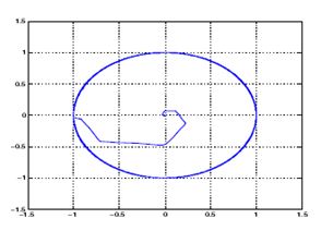
Figure 3: Stator d-q flux space vector without flux optimization                     


 Figure 4: Stator d-q flux space vector with flux  optimization
                                  
Figure 5: Variation of Stator Flux – Conventional  DTC Scheme                                                                   
                                    

  Fig 6: Variation of Stator Flux - Optimized DTC scheme


Figure 7: Variation of Mechanical Speed – Conventional  optimized DTC scheme    


 Figure 8: Variation of Mechanical Speed - Optimized DTC scheme


Figure 9: Electromagnetic Torque - Conventional DTC


Figure 10: Electromagnetic Torque - Optimized  DTC
                                   
Figure 11: Percentage Efficiency of Flux Optimized DTC

CONCLUSION:

In this paper, DTC for an induction motor drive has been shown along with flux optimization algorithm. DTC is a high performance, robust control structure. A comparative analysis of the two DTC schemes, with and without flux optimization algorithm has been presented. With flux optimization implementation, it is observed that the efficiency of the about 87 % has been obtained. MATLAB simulation of a 15 Hp IM drive has been presented to confirm the results.

REFERENCES:

[1] Werner Leonhard. Control of Electric Drives. Springer-Verlag Berlin Heidelberg, 1996.
[2] F. Blaschke. “The Principle of Field Orientation as Applied to The New Transvector Closed Loop Control System for Rotating Field Machines”. Siemens Review, pages 217–220, 1972.
[3] K. Hasse. “On The Dynamic Behavior of Induction Machines Driven by Variable Frequency and Voltage Sources”. ETZ Archive, pages 77–81., 1968.
[4] I. Takahashi and T Nogushi. “A New Quick Reponse and High Efficiency Control Strategy of an Induction Motor”. IEEE Trans. Industry Applications, IA -22:820–827, 1986.

[5] M. Depenbrock. “Direct Self Control (DSC) of inverter-fed induction machines”. IEEE Trans. Power Electronics, 3(4):420–429, 1988

Control Strategies for Wind-Farm-Based Smart Grid System


ABSTRACT:

To incorporate the abundance of renewable energy into the power system, it is required to reconfigure the energy system. An intelligent power grid such as the smart grid is the solution for future energy demand. Among several renewable sources, the wind energy conversion system (WECS) is the rapidly growing source of energy, which is considered as the backbone of renewable energy and the smart grid. This paper deals with control strategies of distributed wind farms that are connected to smart houses for a smart grid application. A grid-side energy storage system is considered to deliver smooth power to the system. Stable control strategies under the line fault condition are also discussed in this paper. The surplus power of the smart houses is sent back to the power grid, and a house owner can benefit by selling the extra power to the power company. The detailed modeling and control strategies of an intelligent power system are demonstrated in this paper. The effectiveness of the proposedsystem is verified by the extensive numerical simulation results.

KEYWORDS:
1. Doubly fed induction generator
          2. Electric double layer capacitor (EDL)
                                                       3. Fault condition
                                                       4.Power smoothing smart grid
                                                       5.Smart house
                                                       6. Wind farm.
SOFTWARE: MATLAB/SIMULINK

BLOCK DIAGRAM:


Fig. 1. Proposed system configuration

EXPECTED SIMULATION RESULTS:


Fig. 2. Simulation results under the normal condition. (a) Wind speed. (b) Rotational speed of the wind turbine. (c) Wind farm output powers. (d) Different powers of the system. (e) Output power of the EDLC. (f) DC-link voltage of the EDLC. (g) Power of house group-1. (h) Power of house group-2. (i) Power of transformer-1. (j) Power of transformer-2.
 

Fig. 3. Simulation results under the fault condition. (a) Wind speed. (b) Rotor speed. (c) Output power of the wind farm. (d) DC-link voltage of the wind turbine. (e) DC-link voltage of the EDLC. (f) Terminal voltage of the EDLC. (g) Line power of the system.

CONCLUSION:

A wind-farm-based smart grid system coordinated with smart houses has been proposed. Wind velocity is a fluctuating resource, and the generated power of the wind turbine is cubic proportional to the wind speed. Therefore, the output power of the wind turbine is fluctuated. In this paper, an EDLC energy storage is applied to generate a smooth line power for the smart grid system. The line power can be smoothed by the EDLC system extensively. In addition, a stable operation can be performed at the fault condition through the chopper circuit approaches. From the simulation results, the effectiveness of the proposed method is verified.

REFERENCES:

[1] P. Yi, A. Iwayemi, and C. Zhou, “Developing ZigBee deployment guideline under WiFi interference for smart grid applications,” IEEE Trans. Smart Grid, vol. 2, no. 1, pp. 110–120, Mar. 2011.
[2] A. Ipakchi and F. Albuyeh, “Grid of the future,” IEEE Power Energy Mag., vol. 7, no. 2, pp. 52–62, Mar./Apr. 2009.
[3] G. Mandic, A. Nasiri, E. Muljadi, and F. Oyague, “Active torque control for gearbox load reduction in a variable-speed wind turbine,” IEEE Trans. Ind. Appl., vol. 48, no. 6, pp. 2424–2432, Nov./Dec. 2012.
[4] H. Jagau, M. A. Khan, and P. S. Barendse, “Design of a sustainable wind generator system using redundant materials,” IEEE Trans. Ind. Appl., vol. 48, no. 6, pp. 1827–1837, Nov./Dec. 2012.

[5] A.M. Howlader et al., “A minimal order observer based frequency control strategy for an integrated wind–battery–diesel power system,” Energy,vol. 46, no. 1, pp. 168–178, Oct. 2012.

Tuesday 2 February 2016

An Adaptive Control Strategy for Low Voltage Ride Through Capability Enhancement of Grid-Connected Photovoltaic Power Plants


ABSTRACT:

This paper presents a novel application of continuous mixed -norm (CMPN) algorithm-based adaptive control strategy with the purpose of enhancing the low voltage ride through (LVRT) capability of grid-connected photovoltaic (PV) power plants. The PV arrays are connected to the point of common coupling (PCC) through a DC-DC boost converter, a DC-link capacitor, a gridside inverter, and a three-phase step up transformer. The DC-DC converter is used for a maximum power point tracking operation based on the fractional open circuit voltage method. The grid-side inverter is utilized to control the DC-link voltage and terminal voltage at the PCC through a vector control scheme. The CMPN algorithm-based adaptive proportional-integral (PI) controller is used to control the power electronic circuits due to its very fast convergence. The proposed algorithm updates the PI controller gains online without the need to fine tune or optimize. For realistic responses, the PV power plant is connected to the IEEE 39-bus New England test system. The effectiveness of the proposed control strategy is compared with that obtained using Taguchi approach- based an optimal PI controller taking into account subjecting the system to symmetrical, unsymmetrical faults, and unsuccessful reclosing of circuit breakers due to the existence of permanent fault. The validity of adaptive control strategy is extensively verified by the simulation results, which are carried out using PSCAD/EMTDC software. With the proposed adaptive-controlled PV power plants, the LVRT capability of such system can be improved

KEYWORDS:

1.      Adaptive control
2.       Low voltage ride through (LVRT)
3.       Photovoltaic (PV) power systems
4.       Power system control
5.      Power system dynamic stability

SOFTWARE: MATLAB/SIMULINK

BLOCK DIAGRAM:
    

Fig. 1. Grid-connected PV power plant. (a) Connection of PV power plant. (b) Single line diagram of the IEEE 39-bus New England test system.


EXPECTED SIMULATION RESULTS:


 Fig. 2. Responses for 3LG temporary fault. (a) Vpcc. (b) Real power out of the PCC. (c) Reactive power out of the PCC. (d)Vdc. (e) Voltage at bus 18. (f) Inverter currents with the proposed controller.


Fig. 3. Vpcc response for unsymmetrical faults. (a) 2LG fault. (b) LL fault. (c) 1LG fault.


Fig. 4. Responses for 3LG permanent fault. (a) Vpcc. (b) Real power out of the PCC. (c) Reactive power out of the PCC. (d) Vdc.

CONCLUSION:

This paper has introduced a novel application of the CMPN algorithm-based adaptive PI control strategy for enhancing the LVRT capability of grid-connected PV power plants. The proposed control strategy was applied to the DC-DC boost converter for a maximum power point tracking operation and also to the grid-side inverter for controlling the Vpcc and Vdc. The CMPN adaptive filtering algorithm was used to update the proportional and integral gains of the PI controller online without the need to fine tune or optimize. For realistic responses, the PV power plant was connected to the IEEE 39-bus New England test system. The simulation results have proven that the system responses using the CMPN algorithm-based adaptive control strategy are faster, better damped, and superior to that obtained using Taguchi approach-based an optimal PI control scheme during the following cases:
1) subject the system to a symmetrical 3LG temporary fault;
2) subject the system to different unsymmetrical faults;
3) subject the system to a symmetrical 3LG permanent fault and unsuccessful reclosure of CBs.
It can be claimed from the simulation results that the LVRT capability of grid-connected PV power plants can be further enhanced using the proposed adaptive control strategy whatever under grid temporary or permanent fault condition. By this way, the PV power plants can contribute to the grid stability and reliability, which represents a greater challenge to the network operators. Moreover, the proposed algorithm can be also applied to other renewable energy systems for the same purpose.

REFERENCES:

[1] PV Power Plants 2014 Industry Guide [Online]. Available: http://www. pvresources.com
[2] D. L. Brooks and M. Patel, “Panel: Standards & interconnection requirements for wind and solar generation NERC integrating variable generation task force,” in Proc. IEEE Power Eng. Soc. General Meeting 2011, Jul. 2011, pp. 1–3.
[3] G. J. Kish, “Addressing future grid requirements for distributed energy resources,” M.Sc. thesis, Dept. Elect. Comput. Eng., Univ. Toronto, Toronto, ON, Canada, 2011.
[4] Y. Yang, F. Blaabjerg, and Z. Zou, “Benchmarking of grid fault modes in single-phase grid-connected photovoltaic systems,” IEEE Trans. Ind. Applicat., vol. 49, no. 5, pp. 2167–2176, Sep./Oct. 2013.
[5] Y. Yang, F. Blaabjerg, and H. Wang, “Low-voltage ride-through of single-phase transformerless photovoltaic inverters,” IEEE Trans. Ind. Applicat., vol. 50, no. 3, pp. 1942–1952, May/Jun. 2014.

Monday 18 January 2016

Evaluation and selection of AC transmission lay-outs for large offshore wind farms


 ABSTRACT:
This paper studies different energy transmission solutions for AC offshore wind farms. This transmission of energy is based on AC submarine cables that present a strong capacitive behavior. Therefore, an analysis is necessary to determine transmission characteristics such as, the number of submarine cables, voltage or rated power. For that purpose, three different transmission configurations will be considered: unique HVAC, various HVAC and MVAC, combined with three submarine cables of different characteristics. By using a design procedure, it is shown that based on the electric characteristics provided by the manufacturer of the submarine cable, it is possible to determine the most efficient energy transmission solution, from the perspective of the submarine cable. Different variables will be taken into account, including transmission current, active power losses, the cost of the transmitted energy and the reactive power compensation required. In addition, the consequences of the selected transmission solution to other more general aspects of the wind farm such as, necessity of the offshore platform or local inter turbine network are also discussed.

KEYWORDS:

1.      Wind energy
2.       Transmission of electrical energy
3.       AC-cable

SOFTWARE: MATLAB/SIMULINK

BLOCK DIAGRAMS:


Fig. 1: General layout of HVAC offshore wind farm.
          
Fig. 2: General layout of MVAC offshore wind farm.
            
Fig. 3: General layout of offshore wind farm with multiple HVAC connections.


EXPECTED SIMULATION RESULTS:
  

Fig. 4: Module of the current through the submarine cable vs cable length. With compensation at both ends (red) and onshore compensation (blue). a) 5x30MW-36kV configuration. b) 150MW 150Kv
Fig. 5: Active power losses for 50km cable length, with compensation at both ends (red) and onshore compensation (blue) a) 150MW-150kV, 2x75MW-87kV, 3x50MW-66kV y 5x30MW-36kV configurations b) 150MW-220kV
Fig. 6: a) Rayleigh distribution for different average wind speeds b) Generated power on wind farm on function of the wind speed.
                     
Fig. 7: Energy transmission cost for different layouts.

CONCLUSION:
In agreement with built wind farms, a MVAC transmission system is the best option near to shore. This is because submarine cables are very expensive. With big cable lengths the cables costs do not compensate the money saved in the offshore platform. With short cable lengths (<20Km) MVAC connections are better than other layouts. Moreover, at 150 MW rated power MVAC configuration can be the best option to 60Km cable length. However in this case the clusters are of (40-50MW) and the submarine cables operates at 70-80% (or more depending the cable length) of their load capability. This can cause an inadmissible voltage drop in the transmission system or other harmful effects. In this paper only conduction losses in the submarine cables have been considered, armor losses or dielectric losses have also not been taken into account. But this simplification affect to cable parameterization and not to layout selection procedure. 220kV HVAC system is not the best option for any cable length. But the cable used in this evaluation has 3 times higher resistive component than other cables.
REFERENCES:
[ 1 ] S. Lundberg, "Wind farm configuration and energy efficiency studies series DC versus AC layouts," Thesis, Chalmers University of Technology 2006.
[ 2 ] S. Lundberg, "Evaluation of wind farm layouts," EPE Journal (European Power Electronics and Drives Journal), vol. 16, pp. 14-20, 2006.
[ 3 ] Ã…. Larsson, A. Petersson, N. Ullah, O. Carlson, “Krieger’s Flak Wind Farm”, Nordic wind power conference, May 2006
[ 4 ] S.D. Wright, A.L. Rogers, J.F. Manwell, A. Ellis, “Transmision options for offshore wind farms in the united states,” AWEA 2002
[ 5 ] S. Chondrogiannis, M. Barnes, “Technologies for integrating wind farms to the grid (Intering report)”, DTI 2006.


Analysis and Comparison of Medium Voltage High Power DC/DC Converters for Offshore Wind Energy Systems


ABSTRACT:
Offshore wind farm with an internal medium-voltage dc (MVDC)-grid collection connected HVDC transmission may be an option to harvest offshore wind energy. High-power MV dc/dc converters with high-step-up conversion ratios are the key components for the internal MVDC grid. In this paper, a high efficiency step-up resonant switched-capacitor converter for offshore wind energy system is studied, which is characterized by the soft-switching condition for all switches and diodes. This significantly reduces switching losses and higher switching frequency
is feasible to reduce the overall system volume and weight. The comparisons with other two kinds of topologies are also presented; moreover, the possible specification requirements of high power MV dc/dc converters are analyzed and set. The operation principle of the proposed converter has been successfully verified by simulation and experiment results.

KEYWORDS:

1.      High power
2.      Medium-voltage dc (MVDC) converter
3.      MVDC grid
4.      Offshore wind farm

SOFTWARE: MATLAB/SIMULINK

BLOCK DIAGRAMS:


 Fig.1. Layouts of three kinds of electrical systems for offshore wind farms. (a) AC system. (b) AC/DC system. (c) DC system.
CIRCUIT DIAGRAM:


Fig. 2. Configuration of the proposed ZCS RSC converter.

EXPECTED SIMULATION RESULTS:


Fig. 3. Idealized waveforms of Fig. 2.

 
Fig. 4. Simulation waveforms of an 8-level SCR converter.


Fig. 5. Experimental waveforms under full-load condition. (a) Vgs and Vds of Q1 , currents of Lp1 and Ln 1 . (b) Vgs and Vds of Q1 , currents of Lp5 and Lp2 . (c) Vgs and Vds of Q1 , currents of Dp12 and Dp11 . (d) Vgs and Vds of Q1 , currents of Dp52 and Dp51 .


CONCLUSION:

High-power MV dc/dc converters with high-step-up conversion ratios are the key components in MVDC-grid collection systems for offshore wind farms. This paper has studied the possible specification requirements of high power MV dc/dc converters. A high efficiency step-up resonant switched-capacitor converter for offshore wind energy system has been proposed, which significantly reduces switching losses, increases switching frequency and minimizes the overall system volume. The operation principle and detailed design of the main circuit are presented. The experimental results from the prototype have confirmed the feasibility of the proposed converter.

REFERENCES:

[1] P. K. Steimer and O. Apeldoorn, “Medium voltage power conversion technology for efficient windpark power collection grids,” in Proc. IEEE Int. Symp. Power Electron. Distrib. Gener. Syst., Jun. 2010, pp. 12–18.
[2] S. M. Muyeen, R. Takahashi, and J. Tamura, “Operation and control of HVDC-connected offshore wind farm,” IEEE Trans. Sustainable Energy, vol. 1, no. 1, pp. 30–37, Apr. 2010.
[3] O.Martander, “DC grid for wind farms,” Licentiate of Engineering Thesis, Dept. of EPE, Chalmers University of Technology, Landala, Sweden, 2002.
[4] C. Meyer, M. H¨oing, A. Peterson, and R. W. De Doncker, “Control and design of DC grid for offshore wind farms,” IEEE Trans. Ind. Appli., vol. 43, no. 6, pp. 1474–1482, Nov./Dec. 2007.
[5] J. Robinson, D. Jovcic, and G. Jo´os, “Analysis and design of an offshore wind farm using a MV DC grid,” IEEE Trans. Power Deliv., vol. 25, no. 4, pp. 2164–2173, Oct. 2010.