ABSTRACT:
Control of induction motor is most precisely required
in many high performance applications. With the development in power electronic
field various control methods for control of induction motor have been
developed. Among these Direct torque control (DTC) seems to be particularly
interesting, being independent of machine rotor parameters and requiring no speed
or position sensors. In addition to the simple structure it also allows a good
torque control in transient and steady state conditions. The disadvantage of
using DTC is that it results in high torque and flux ripple and variable
switching frequency of voltage source inverter, owing to the use of hysteresis
controllers for torque and flux loop. In order to overcome these problems, various
methods have been proposed by several researchers like variable hysteresis band
comparators, space vector modulation, predictive control schemes and
intelligent control techniques. However these methods have diminished the main
feature of DTC that is simple control structure. This report presents constant
switching frequency based torque and flux controllers to replace conventional
hysteresis based controllers where almost fixed switching frequency with
reduced torque and flux ripple is obtained by comparing the triangular
waveforms with the compensated error signals
KEYWORDS:
1.3-phase VSI
2. torque controller
3.
flux controller
SOFTWARE: MATLAB/SIMULINK
BLOCK DIAGRAM:

Fig.1.
Block diagram of conventional DTC method

Fig.2. MATLAB/SIMULINK Model of
the DTC Drive
EXPECTED SIMULATION RESULTS:

Fig.3.
Torque response (a) Conventional DTC scheme (b) Improved DTC Scheme

Fig.4.
Speed and Torque response for (a) Conventional DTC scheme (b) Improved DTC
scheme

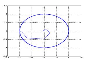
Fig.5.
Circular flux locus (a) conventional DTC scheme (b) Improved DTC scheme

Fig.6.
3-phase line-line voltages and currents (a) Conventional DTC scheme (b)
Improved DTC scheme
CONCLUSION:
In
this paper a detailed comparison between the conventional DTC and improved DTC
scheme is made with help of some Matlab simulation results and hence it is
shown that a significant reduction in torque and flux ripple can be achieved
with the improved DTC scheme also with improved controllers the switching
frequency which is constant can be varied by varying the frequency of the
triangular carrier waveforms of the torque controllers
REFERENCES:
[1] I. Takahashi and T. Noguchi, “A new quick-response and high efficiency
control strategy of an induction motor,” IEEE Trans. Ind. Appl., vol. IA-22,no. 5, pp. 820–827, Sep.–Oct.
1986.
[2] J-K. Kang, D-W Chung, S. K. Sul, (2001) “Analysis and
prediction of inverter switching frequency in direct torque control of
induction machine based on hysteresis bands and machine parameters”, IEEE Transactions on Industrial Electronics,
Vol. 48, No. 3, pp. 545-553.
[3] D.Casadei, G.Gandi,G.Serra,A.Tani,(1994)“Switching
strategies in direct torque control of induction machines,” in Proc. of ICEM’94, Paris (F), pp. 204-209.
[4] J-K. Kang, D-W Chung and S.K. Sul, (1999) “Direct torque
control of induction machine with variable amplitude control of flux and torque
hysteresis bands”, International Conference on Electric Machines and Drives
IEMD’99,pp.640-642.
[5] Vanja Ambrozic, Giuseppe S. Buja, and Roberto Menis, ”Band- Constrained Technique for Direct
Torque Control of Induction Motor”, IEEE Trans. On industrial electronics ,
vol. 51, no. 4, august 2004, pp.776-784