asokatechnologies@gmail.com 09347143789/09949240245

Search This Blog

Tuesday 21 June 2016

Distributed Voltage Control with Electric Springs: Comparison with STATCOM


ABSTRACT:
 The concept of ‘Electric Spring (ES)’ has been proposed recently as an effective means of distributed voltage control. The idea is to regulate the voltage across the ‘critical loads’ while allowing the ‘non-critical’ impedance-type loads (e.g. water heaters) to vary their power consumption and thus contribute to demand-side response. In this paper a comparison is made between distributed voltage control using ES against the traditional single point control with STATCOM. For a given range of supply voltage variation, the total reactive capacity required for each option to produce the desired voltage regulation at the point of connection is compared. A simple case study with a single ES and STATCOM is presented first to show that the ES and STATCOM require comparable reactive power to achieve similar voltage regulation. Comparison between a STATCOM and ES is further substantiated through similar case studies on the IEEE 13-bus test feeder system and also on a part of the distribution network in Sha Lo Wan Bay, Hong Kong. In both cases, it turns out that a group of ESs achieves better total voltage regulation than STATCOM with less overall reactive power capacity. Dependence of the ES capability on proportion of critical and non-critical load is also shown.
KEYWORDS:

1.      Demand response
2.       Electric springs
3.       STATCOM
4.       Voltage control
5.       Voltage regulation

SOFTWARE: MATLAB/SIMULINK

BLOCK DIAGRAM:
                                          

Fig. 1. Electric Spring set-up for Smart loads.


Fig. 2. Simulation set up with an intermittent source and an equivalent power grid.


EXPECTED SIMULATION RESULTS:


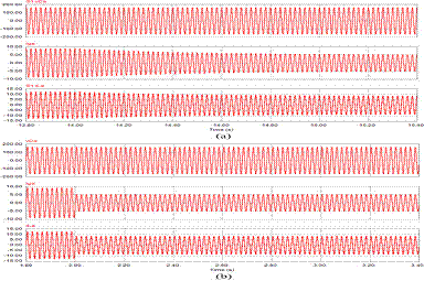
Fig. 3. System response following decrease in reactive power consumption of the intermittent source from 467 to 110 VAr


Fig. 4. System response following increase in reactive power consumption of the intermittent source from 1100 to 467 VAr.


Fig. 5. System response for different distribution of non-critical and critical loads (NC:C). Disturbance is increase in reactive power consumption of the intermittent source from 467 to 1100 VAr.

CONCLUSION:
In this paper a comparison is made between distributed voltage control using ES against the traditional single point control with STATCOM. For a given range of supply voltage variation, the total voltage regulation and the total reactive capacity required for each option to produce the desired voltage regulation at the point of connection are compared. A simple case study with a single ES and STATCOM is presented first to show that the ES and STATCOM require comparable reactive power to achieve similar voltage regulation. Comparison between a STATCOM and ES is further substantiated through similar case studies on the IEEE 13-bus test feeder system and also on a part of the distribution network in Sha Lo Wan Bay, Hong Kong. In both cases, it turns out that the ESs requires less overall reactive power capacity than STATCOM and yields better total voltage regulation. This makes electric springs (ESs) a promising technology for future smart grids where selective voltage regulation for sensitive loads would be necessary alongside demand side response.
REFERENCES:
[1] N. G. Hingorani and L. Gyugyi, Understanding FACTS : concepts and technology of flexible AC transmission systems. New York: IEEE Press, 2000.
[2] S. Y. Hui, C. K. Lee, and F. F. Wu, "Electric Springs: A New Smart Grid Technology," Smart Grid, IEEE Transactions on, vol. 3, pp. 1552-1561, 2012.
[3] A. Brooks, E. Lu, D. Reicher, C. Spirakis, and B. Weihl, "Demand Dispatch," IEEE Power and Energy Magazine,, vol. 8, pp. 20-29, 2010.
[4] D. Westermann and A. John, "Demand Matching Wind Power Generation With Wide-Area Measurement and Demand-Side Management," IEEE Transactions on Energy Conversion, vol. 22, pp. 145-149, 2007.
[5] C. K. Lee and S. Y. Hui, "Reduction of Energy Storage Requirements in Future Smart Grid Using Electric Springs," Smart Grid, IEEE Transactions on, vol. PP, pp. 1-7, 2013.


Tuesday 14 June 2016

H6-type Single Phase Full-Bridge PV Grid-Tied Transformerless Inverters


ABSTRACT:
Photovoltaic (PV) generation systems are widely employed in transformer less inverters, in order to achieve the benefits of high efficiency and low cost. Safety requirements of leakage currents are met by proposing the various transformers less inverter topologies. In this paper, three transformer less inverter topologies are illustrated such as a family of H6 transformer less inverter topologies with low leakage currents is proposed, and the intrinsic relationship between H5 topology, highly efficient and reliable inverter concept (HERIC) topology. The proposed H6 topology has been discussed as well. For a detailed analysis with operation modes and modulation strategy one of the proposed H6 inverter topologies is taken as an example. Comparison among the HERIC, the H5, and the proposed H6 topologies is been done for the power device costs and power losses. For evaluating their performances in terms of power efficiency and leakage currents characteristics, a universal prototype is built for these three topologies mentioned. Simulation results show that the proposed HERIC topology and the H6 topology achieve similar performance in leakage currents, which is slightly worse than that of the H5 topology, but it features higher efficiency than that of H5 topology.

KEYWORDS:
1.      Common-mode voltage
2.       Grid-tied inverter
3.       Leakage current
4.       Photovoltaic (PV) generation system
5.       Transformerless inverter

SOFTWARE: MATLAB/SIMULINK

BLOCK DIAGRAM:


Fig. 1. Leakage current path for transformerless PV inverters

EXPECTED SIMULATION RESULTS:


Fig. 2. CM voltage and leakage current in H6 topology. (a) CM voltage. (b) Leakage current.


Fig. 3. Drain–source voltages in H6 topology. (a) Voltage stress on S5 and S6 . (b) Detailed waveforms.


Fig. 4. DM characteristic of H6 topology.


Fig. 5. Efficiency comparison of H5, HERIC and H6 topologies.

             
CONCLUSION:

In this paper, based on the H5 topology, a new current path is formed by inserting a power device between the terminals of PV array and the midpoint of one of bridge legs. As a result, a family of single-phase transformerless full-bridge H6 inverter topologies with low leakage currents is derived. The proposed H6 topologies have the following advantages and evaluated by simulation results:
1) The conversion efficiency of the novel H6 topology is better than that of the H5 topology, and its thermal stress distribution is better than that of the H5 topology;
2) The leakage current is almost the same as HERIC topology, and meets the safety standard;
3) The excellent DM performance is achieved like the isolated full-bridge inverter with uniploar SPWM. Therefore, the proposed H6 topologies are good solutions for the single phase transformerless PV grid-tied inverters.

 REFERENCES:
 [1] S. B. Kjaer, J. K. Pederson, and F. Blaabjerg, “A review of single-phase grid-connected inverters for photovoltaic modules,” IEEE Trans. Ind. Appl., vol. 41, no. 5, pp. 1292–1306, Sep/Oct. 2005.
[2] F. Blaabjerg, Z. Chen, and S. B. Kjaer, “Power electronics as efficient interface in dispersed power generation systems,” IEEE Trans. Power Electron., vol. 19, no. 5, pp. 1184–1194, Sep. 2004.
[3] B. Sahan, A. N. Vergara, N. Henze, A. Engler, and P. Zacharias, “A single stage PVmodule integrated converter based on a low-power current source inverter,” IEEE Trans. Ind. Electron., vol. 55, no. 7, pp. 2602–2609, Jul.2008.
[4] M. Calais, J. Myrzik, T. Spooner, and V. G. Agelidis, “Inverters for single phase grid connected photovoltaic systems—An overview,” in Proc. IEEE PESC, 2002, vol. 2, pp. 1995–2000.
[5] F. Blaabjerg, Z. Chen, and S. B. Kjaer, “Power electronics as efficient interface in dispersed power generation systems,” IEEE Trans. Power Electron., vol. 19, no. 5, pp. 1184–1194, Sep. 2004.


Monday 13 June 2016

A Unified Control Strategy for Three-Phase Inverter in Distributed Generation

ABSTRACT:
This paper presents a unified control strategy that enables both islanded and grid-tied operations of three-phase inverter in distributed generation, with no need for switching between two corresponding controllers or critical islanding detection. The proposed control strategy composes of an inner inductor current loop, and a novel voltage loop in the synchronous reference frame. The inverter is regulated as a current source just by the inner inductor current loop in grid-tied operation, and the voltage controller is automatically activated to regulate the load voltage upon the occurrence of islanding. Furthermore, the waveforms of the grid current in the grid-tied mode and the load voltage in the islanding mode are distorted under nonlinear local load with the conventional strategy. And this issue is addressed by proposing a unified load current feedforward in this paper. Additionally, this paper presents the detailed analysis and the parameter design of the control strategy. Finally, the effectiveness of the proposed control strategy is validated by the simulation results.

KEYWORDS:
1.      Distributed generation (DG)
2.      Islanding
3.      Load current
4.      Seamless transfer
5.      Three-phase inverter
6.       Unified control

SOFTWARE: MATLAB/SIMULINK

BLOCK DIAGRAM:


Fig. 1. Overall block diagram of the proposed unified control strategy.

EXPECTED SIMULATION RESULTS:
Fig. 2. Simulation waveforms of load voltage vC a , grid current iga, and inductor current iLa when DG is in the grid-tied mode under condition of the step down of the grid current reference from 9 A to 5 A with: (a) conventional
voltage mode control, and (b) proposed unified control strategy.

Fig. 3. Simulation waveforms of load voltage vC a , grid current iga, and inductor current iLa when DG is transferred from the grid-tied mode to the islanded mode with: (a) conventional hybrid voltage and current mode control, and (b) proposed unified control strategy.


CONCLUSION:

A unified control strategy was proposed for three-phase inverter in DG to operate in both islanded and grid-tied modes, with no need for switching between two different control architectures or critical islanding detection. A novel voltage controller was presented. It is inactivated in the grid-tied mode, and the DG operates as a current source with fast dynamic performance. Upon the utility outage, the voltage controller can automatically be activated to regulate the load voltage. Moreover, a novel load current feed forward was proposed, and it can improve the waveform quality of both the grid current in the grid-tied mode and the load voltage in the islanded mode. The proposed unified control strategy was verified by the simulation results.

REFERENCES:
 [1] R. C. Dugan and T. E. McDermott, “Distributed generation,” IEEE Ind. Appl. Mag., vol. 8, no. 2, pp. 19–25, Mar./Apr. 2002.
[2] R. H. Lasseter, “Microgrids and distributed generation,” J. Energy Eng., vol. 133, no. 3, pp. 144–149, Sep. 2007.
[3] C. Mozina, “Impact of green power distributed generation,” IEEE Ind. Appl. Mag., vol. 16, no. 4, pp. 55–62, Jul./Aug. 2010.
[4] IEEE Recommended Practice for Utility Interface of Photovoltaic(PV) Systems, IEEE Standard 929-2000, 2000.
[5] IEEE Standard for Interconnecting Distributed Resources with Electric Power Systems, IEEE Standard 1547-2003, 2003.


Monday 6 June 2016

A Switched-Capacitor Inverter Using Series/Parallel Conversion with Inductive Load


ABSTRACT
A novel switched-capacitor inverter is proposed. The proposed inverter outputs larger voltage than the input voltage by switching the capacitors in series and in parallel. The maximum output voltage is determined by the number of the capacitors. The proposed inverter, which does not need any inductors, can be smaller than a conventional two-stage unit which consists of a boost converter and an inverter bridge. Its output harmonics are reduced compared to a conventional voltage source single phase full bridge inverter. In this paper, the circuit configuration, the theoretical operation, the simulation results with MATLAB/ SIMULINK, and the experimental results are shown. The experimental results accorded with the theoretical calculation and the simulation results.

KEYWORDS
1.      Charge pump
2.       Multicarrier PWM
3.       Multilevel Inverter
4.       Switched capacitor (SC)

SOFTWARE: MATLAB/SIMULINK

 BLOCK DIAGRAM:

Fig. 1. Circuit topology of the switched-capacitor inverter using series/ parallel conversion.

EXPECTED SIMULATION RESULTS


Fig. 2. Simulated voltage waveforms of the proposed inverter (n = 2) designed for high power at 4.50 [kW], switching frequency f = 40 [kHz] and reference waveform frequency fref = 1 [kHz]. (a) Bus voltage waveform vbus and (b) the output voltage waveform vout.

Fig. 3. Simulated current waveforms of the capacitor iC1 in the proposed inverter (n = 2).(a) Designed for low power at 5.76 [W] and (b) designed for high power at 4.50 [kW].

Fig. 4. Simulated spectra of the bus voltage waveform of the proposed inverters (n = 2) normalized with the fundamental component. (a) Designed for low power at 5.76 [W] and (b) designed for high power at 4.50 [kW].

Fig. 5. Simulated bus voltage waveforms vbus and the voltage waveforms of the load resistance vR of the proposed inverter (n = 2) designed for low power at 5.76 [W] with an inductive load.


Fig. 6. Experimental circuit

Fig. 7. Observed bus voltage waveform vbus. Vertical 10 [V/div], horizontal
250 [μs/div].


Fig. 8. Observed output voltage waveform vout. Vertical 10 [V/div],
horizontal 250 [μs/div].

Fig. 9. Observed spectrum of the bus voltage waveform.


Fig. 10. Observed current waveform of the capacitor iC1. Vertical 500 [mA/div], horizontal 250 [μs/div]

Fig. 11. Observed voltage waveforms vbus and vR with an inductive load.
Vertical 10 [V/div], horizontal 250 [μs/div].
CONCLUSION

In this paper, a novel boost switched-capacitor inverter was proposed. The circuit topology was introduced. The modulation method, the determination method of the capacitance, and the loss calculation of the proposed inverter were shown. The circuit operation of the proposed inverter was confirmed by the simulation results and the experimental results with a resistive load and an inductive load. The proposed inverter outputs a larger voltage than the input voltage by switching the capacitors in series and in parallel. The inverter can operate with an inductive load. The structure of the inverter is simpler than the conventional switched-capacitor inverters. THD of the output waveform of the inverter is reduced compared to the conventional single phase full bridge inverter as the conventional multilevel inverter.

REFERENCES

[1] H. Liu, L. M. Tolbert, S. Khomfoi, B. Ozpineci, and Z. Du, “Hybrid cascaded multilevel inverter with PWM control method,” in Proc. IEEE Power Electron. Spec. Conf., Jun. 2008, pp. 162–166.
[2] A. Emadi, S. S. Williamson, and A. Khaligh, “Power electronics intensive solutions for advanced electric, hybrid electric, and fuel cell vehicular power systems,” IEEE Trans. Power Electron., vol. 21, no. 3, pp. 567–577, May 2006.
[3] L. G. Franquelo, J. Rodriguez, J. I. Leon, S. Kouro, R. Portillo, and M. A. M. Prats, “The age of multilevel converters arrives,” IEEE Ind. Electron. Mag., vol. 2, no. 2, pp. 28–39, Jun. 2008.
[4] Y. Hinago and H. Koizumi, “A single phase multilevel inverter using switched series/parallel DC voltage sources,” IEEE Trans. Ind. Electron., vol. 57, no. 8, pp. 2643–2650, Aug. 2010.
[5] S. Chandrasekaran and L. U. Gokdere, “Integrated magnetics for interleaved DC–DC boost converter for fuel cell powered vehicles,” in Proc. IEEE Power Electron. Spec. Conf., Jun. 2004, pp. 356–361.
[6] Y. Hinago and H. Koizumi, “A switched-capacitor inverter using series/ parallel conversion,” in Proc. IEEE Int. Symp. Circuits Syst., May/Jun. 2010, pp. 3188–3191.
[7] J. A. Starzyk, Y. Jan, and F. Qiu, “A dc–dc charge pump design based on voltage doublers,” IEEE Trans. Circuits Syst. I, Fundam. Theory Appl., vol. 48, no. 3, pp. 350–359, Mar. 2001.
[8] M. R. Hoque, T. Ahmad, T. R. McNutt, H. A. Mantooth, and M. M. Mojarradi, “A technique to increase the efficiency of high-voltage charge pumps,” IEEE Trans. Circuits Syst. II, Exp. Briefs, vol. 53, no. 5, pp. 364–368, May 2006.
[9] O. C.Mak and A. Ioinovici, “Switched-capacitor inverter with high power density and enhanced regulation capability,” IEEE Trans. Circuits Syst. I, Fundam. Theory Appl., vol. 45, no. 4, pp. 336–347, Apr. 1998.
[10] B. Axelrod, Y. Berkovich, and A. Ioinovici, “A cascade boost-switchedcapacitor- converter-two level inverter with an optimized multilevel output waveform,” IEEE Trans. Circuits Syst. I, Reg. Papers, vol. 52, no. 12, pp. 2763–2770, Dec. 2005.
[11] J. I. Rodriguez and S. B. Leeb, “A multilevel inverter topology for inductively coupled power transfer,” IEEE Trans. Power Electron., vol. 21, no. 6, pp. 1607–1617, Nov. 2006.
[12] X. Kou, K. A. Corzine, and Y. L. Familiant, “A unique fault-tolerant design for flying capacitor multilevel inverter,” IEEE Trans. Power Electron., vol. 19, no. 4, pp. 979–987, Jul. 2004.
[13] S. Lu, K. A. Corzine, andM. Ferdowsi, “A unique ultracapacitor direct integration scheme in multilevel motor drives for large vehicle propulsion,” IEEE Trans. Veh. Technol., vol. 56, no. 4, pp. 1506–1515, Jul. 2007.
[14] J. I. Leon, S. Vazquez, A. J. Watson, L. G. Franquelo, P. W. Wheeler, and J. M. Carrasco, “Feed-forward space vector modulation for single-phase multilevel cascaded converters with any dc voltage ratio,” IEEE Trans. Ind. Electron., vol. 56, no. 2, pp. 315–325, Feb. 2009.
[15] B. P. McGrath and D. G. Holmes, “Multicarrier PWM strategies for multilevel inverters,” IEEE Trans. Ind. Electron., vol. 49, no. 4, pp. 858–867, Aug. 2002.
[16] R. Gupta, A. Ghosh, and A. Joshi, “Switching characterization of cascaded multilevel-inverter-controlled systems,” IEEE Trans. Ind. Electron., vol. 55, no. 3, pp. 1047–1058, Mar. 2008.
[17] J. Zhang, Y. Zou, X. Zhang, and K. Ding, “Study on a modified multilevel cascade inverter with hybrid modulation,” in Proc. IEEE Power Electron. Drive Syst., Oct. 2001, pp. 379–383.
[18] V. G. Agelidis, A. I. Balouktsis, and C. Cossar, “On attaining the multiple solutions of selective harmonic elimination PWM three-level waveforms through function minimization,” IEEE Trans. Ind. Electron., vol. 55, no. 3, pp. 996–1004, Mar. 2008.
[19] J. A. Pontt, J. R. Rodriguez, A. Liendo, P. Newman, J. Holtz, and J. M. San Martin, “Network-friendly low-switching-frequency multipulse high-power three-level PWM rectifier,” IEEE Trans. Ind. Electron., vol. 56, no. 4, pp. 1254–1262, Apr. 2009.

[20] M. K. Kazimierczuk, “Switching losses with linear MOSFET output capacitance,” in Pulse-Width Modulated DC–DC Power Converters, 1st ed. West Sussex, U.K.: Wiley, 2008, ch. 2, pp. 37–38, sec. 2.

Wednesday 1 June 2016

An Advanced Power Electronics Interface for Electric Vehicles Applications


Abstract
Power electronics interfaces play an increasingly important role in the future clean vehicle technologies. This paper proposes a novel integrated power electronics interface (IPEI) for battery electric vehicles (BEVs) in order to optimize the performance of the power train. The proposed IPEI is responsible for the power-flow management for each operating mode. In this paper, an IPEI is proposed and designed to realize the integration of the dc/dc converter, on-board battery charger, and dc/ac inverter together in the BEV power train with high performance. The proposed concept can improve the system efficiency and reliability, can reduce the current and voltage ripples, and can reduce the size of the passive and active components in the BEV drive trains compared to other topologies. In addition, low electromagnetic interference and low stress in the power switching devices are expected. The proposed topology and its control strategy are designed and analyzed by using MATLAB/Simulink. The simulation results related to this research are presented and discussed. Finally, the proposed topology is experimentally validated with results obtained from the prototypes that have been built and integrated in our laboratory based on TMS320F2808 DSP.

Keywords

1.      Battery electric vehicles (BEVs)
2.      interleaved dc/dc converter
3.       on-board battery charger
4.      Power train control strategies
5.       Power train modeling
6.       small-signal model

Software: MATLAB/SIMULINK

Block Diagram:


Fig. 1. Schematic diagram of the battery electric vehicles.
Expected Simulation Results:

Fig2. Dynamic performance of the battery pack and the proposed IPEI (simulation result).

Fig3. Comparative efficiency of the ac drive system (Motor & ESI) in the
proposed powertrain (simulation result).


Fig4. Efficiencies of the power electronics interfaces in the proposed power train
(simulation result).

Fig5. Power train efficiency without including the battery efficiency (simulation
result).
Conclusion
In this paper, a novel integrated power electronic interface has been proposed for BEVs to optimize the performance of the powertrain. The proposed IPEI combines the features of the BMDIC and the ESI. The proposed IPEI and its performance characteristics have been analyzed and presented. Different control strategies are designed to verify the performance of the proposed IPEI during different operating modes. It should be pointed out that the IFOC based on PWM voltage and PSO is more efficient than IFOC based on PWM voltage which is used to drive the EM during traction and braking modes. Moreover, the proposed IPEI can achieve a high power factor correction, and can achieve a low THD for the input current during charging mode from the ac grid. As is clear from the simulation results, the proposed IPEI can reduce the current and voltage ripples, can improve the efficiency and reliability, and can provide a compact size for the BEV power train. Furthermore, the battery lifespan can be increased due to the ripple reduction. Finally, the simulation and experimental results have demonstrated that the proposed IPEI has been successfully realized and it promises significant savings in component count with high performance for BEVs compared to other topologies. Therefore, it can be expected that these topologies can be utilized for development of high efficiency BEV power trains.      

References:

[1] C. C. Chan, A. Bouscayrol, and K. Chen, “Electric, hybrid, and fuel-cell vehicles: Architectures and modeling,” IEEE Trans. Veh. Technol., vol. 59, no. 2, pp. 589–598, Feb. 2010.
[2] C. C. Chan, “The state of the art of electric and hybrid, and fuel cell vehicles,” Proc. IEEE, vol. 95, no. 4, pp. 704–718, Apr. 2007.
[3] A. Emadi, S. S.Williamson, and A. Khaligh, “Power electronics intensive solutions for advanced electric, hybrid electric, and fuel cell vehicular power systems,” IEEE Trans. Power Electron., vol. 21, no. 3, pp. 567– 577, May 2006. electronics and motor drives in electric, hybrid electric, and plug-in hybrid electric vehicles,” IEEE Trans. Ind. Electron, vol. 55, no. 6, pp. 2237–2245, Jun. 2008.
[4] A. Emadi, Y. J. Lee, and K. Rajashekara, “Power

[5] S. S. Raghavan, O. C. Onar, and A. Khaligh, “Power electronic interfaces for future plug-in transportation systems,” IEEE Power Electron. Soc. Newsletter, vol. 23, Third Quarter 2010.