ABSTRACT
In this paper, a simple static var compensating scheme
using a cascaded two-level inverter-based multilevel inverter is proposed. The
topology consists of two standard two-level inverters connected in cascade
through open-end windings of a three-phase transformer. The dc link voltages of
the inverters are regulated at different levels to obtain four-level operation.
The simulation study is carried out in MATLAB/SIMULINK to predict the
performance of the proposed scheme under balanced and unbalanced supply-voltage
conditions. A laboratory prototype is developed to validate the simulation
results. The control scheme is implemented using the TMS320F28335 digital signal
processor. Further, stability behavior of the topology is investigated. The dynamic
model is developed and transfer functions are derived. The system behavior is
analyzed for various operating conditions.
KEYWORDS
1.
DC-link
voltage balance
2.
Multilevel inverter
3.
Power quality
(PQ)
4.
Static
compensator (STATCOM)
SOFTWARE:
MATLAB/SIMULINK
BLOCK DIAGRAM

Fig.
1. Power system and the STATCOM model.
EXPECTED SIMULATION RESULTS

Fig.
2. Frequency response ∆Vdc1(s) /∆δ1(s) at i’q0 =1.02 p.u., δ1=-0.90,δ2=178.90,R1=
80
p.u., R2=60 p.u.
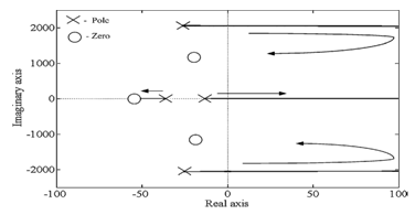
Fig.
3. Root locus of the transfer function ∆Vdc1(s) /∆δ1(s) at i’q0 = - 0.75 p.u., δ1=-0.570,δ2=179.60,R1=
80
p.u., R2=60 p.u.

Fig.
4. Reactive power control. (a) Source voltage and inverter current.
(b)
DC-link voltages of two inverters.

Fig.
5. Operation during fault. (a) Grid voltages on the LV side of the transformer.
(b) -axis negative-sequence current component i’dn. (c)
-axis negative- sequence current component i’qn.
CONCLUSION
DC-link
voltage balance is one of the major issues in cascaded inverter-based STATCOMs.
In this paper, a simple var

Fig. 6.
Experimental result: Capacitive mode of operation. (a) Source voltage (50
V/div) and STATCOM current (5 A/div). (b) DC-link voltages of inverter-1 and inverter-2
(20 V/div). Time scale: 5 ms/div. (c) Harmonic spectrum of
current.

Fig.
7. Experimental result: Mode change from capacitive to inductive. (a) DC-link
voltages of inverter-1 and inverter-2 (20 V/div). Time scale: 100 ms/div. (b)
Source voltage (100 V/div) and STATCOM current (5 A/div) in steady state. Time
scale: 100 ms/div.
compensating
scheme is proposed for a cascaded two-level inverter- based multilevel
inverter. The scheme ensures regulation of dc-link voltages of inverters at
asymmetrical levels and reactive power compensation. The performance of the
scheme is validated by simulation and experimentations under balanced and unbalanced
voltage conditions. Further, the cause for instability when there is a change
in reference current is investigated. The dynamic model is developed and
transfer functions are derived. System behavior is analyzed for various
operating conditions. From the analysis, it is inferred that the system is a
non minimum phase type, that is, poles of the transfer function always lie on
the left half of the -plane. However, zeros shift to the
right
half of the -plane for certain operating conditions. For such a system,
oscillatory instability for high controller gains exists.
REFERENCES
[1]
N. G. Hingorani and L. Gyugyi, Understanding FACTS. Delhi, India: IEEE,
2001, Standard publishers distributors.
[2]
B. Singh, R. Saha, A. Chandra, and K. Al-Haddad, “Static synchronous compensators
(STATCOM): A review,” IET Power Electron., vol. 2, no. 4, pp. 297–324,
2009.
[3]
H. Akagi, H. Fujita, S. Yonetani, and Y. Kondo, “A 6.6-kV transformerless STATCOM
based on a five-level diode-clamped PWMconverter: System design and
experimentation of a 200-V 10-kVA laboratory model,” IEEE Trans. Ind. Appl.,
vol. 44, no. 2, pp. 672–680, Mar./Apr. 2008.
[4]
A. Shukla, A. Ghosh, and A. Joshi, “Hysteresis current control operation of
flying capacitor multilevel inverter and its application in shunt compensation
of distribution systems,” IEEE Trans. Power Del., vol. 22, no. 1, pp.
396–405, Jan. 2007.
[5]
H. Akagi, S. Inoue, and T. Yoshii, “Control and performance of a
transformerless cascaded PWM STATCOM with star configuration,” IEEE Trans.
Ind. Appl., vol. 43, no. 4, pp. 1041–1049, Jul./Aug. 2007.