asokatechnologies@gmail.com 09347143789/09949240245

Search This Blog

Tuesday 28 June 2016

PV-Active Power Filter Combination Supplies Power to Nonlinear Load and Compensates Utility Current


ABSTRACT

The photovoltaic (PV) generation is increasingly popular nowadays, while typical loads require more high-power quality. Basically, one PV generator supplying to nonlinear loads is desired to be integrated with a function as an active power filter (APF). In this paper, a three-phase three-wire system, including a detailed PV generator, dc/dc boost converter to extract maximum radiation power using maximum power point tracking, and dc/ac voltage source converter to act as an APF, is presented. The instantaneous power theory is applied to design the PV-APF controller, which shows reliable performances. The MATLAB/Simpower Systems tool has proved that the combined system can simultaneously inject maximum power from a PV unit and compensate the harmonic current drawn by nonlinear loads.

KEYWORDS
1.      Active power filter (APF)
2.      Instantaneous power theory
3.      Photovoltaic (PV)
4.      Power quality
5.      Renewable energy

SOFTWARE: MATLAB/SIMLINK

 BLOCK DIAGRAM:

Figure 1. proposed design of PV-APF combination.

CONTROL DIAGRAM:

Figure 2. controller topology of dc/ac VSC in the PV-APF combination.

EXPECTED SIMULATION RESULTS:

Figure 3. output power of pv during running time.

Figure 4. duty cycle and vpv changed by mppt. (a) output
voltage of pv unit. (b) duty cycle of mppt.

Figure 5. utility supplied current waveform.

Figure 6. utility supplied current and pcc voltage waveform.

Figure 7. thd in four modes of pv system operation while
utility supplies power. (a) dq-current mode. (b) pv-apf mode.
(c) apf mode. (d) only utility supplies load.

Figure 8. pv supplied current waveform.

Figure 9. real power from the (a) utility, (b) pv unit, and (c)
load, while the utility supplies power.

Figure 10. imaginary power from the (a) utility, (b) pv unit,
and (c) load, while the utility supplies power.

Figure 11. utility received current waveform.


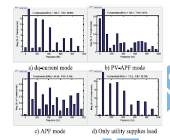
Figure 12. thd in four modes of pv system operation while
utility receives power. (a) dq-current mode. (b) pv-apf mode.
(c) apf mode. (d) only utility supplies load.


Figure 13. real power from the (a) utility, (b) pv unit, and (c)
load, while the utility receives power.

Figure 14. imaginary power from the (a) utility, (b) pv unit,
and (c) load, while the utility receives power.

CONCLUSION:

Regarding the multifunctional DG concept, in this paper, a dynamic grid-connected PV unit is built and the PV-APF combination system with a local controller is proposed. The controller implements two purposes, which are supplying power from the PV unit and filtering the harmonics of the local nonlinear load. The new controller based on instantaneous power balance has been explained accordingly. The MATLAB/Simpower Systems simulation shows good performances of this controller. The positive influence of MPPT on maximizing PV power output is also validated. The switching among three controllers to dc/ac VSC brings different current waveforms. As a result, the conventional dq-current controller should not be applied when PV is connected to a local nonlinear load regarding power-quality viewpoint. Preferably, the PV-APF controller compensates the utility currents successfully. While a PV unit is deactivated, the APF function can still operate. It is, therefore, technically feasible for these power electronics-interfaced DG units to actively regulate the power quality of the distribution system as an ancillary service, which will certainly make those DG units more competitive.

REFERENCES:

[1] L. Hassaine, E. Olias, J. Quintero, and M. Haddadi, ``Digital power factor control and reactive power regulation for grid-connected photovoltaic inverter,'' Renewable Energy, vol. 34, no. 1, pp. 315_321, 2009.
[2] N. Hamrouni, M. Jraidi, and A. Cherif, ``New control strategy for 2-stage grid-connected photovoltaic power system,'' Renewable Energy, vol. 33, no. 10, pp. 2212_2221, 2008.
[3] M. G. Villalva, J. R. Gazoli, and E. R. Filho, ``Comprehensive approach to modeling and simulation of photovoltaic arrays,'' IEEE Trans. Power Electron., vol. 24, no. 5, pp. 1198_1208, May 2009.
[4] N. R. Watson, T. L. Scott, and S. Hirsch, ``Implications for distribution networks of high penetration of compact _uorescent lamps,'' IEEE Trans. Power Del., vol. 24, no. 3, pp. 1521_1528, Jul. 2009.

[5] I. Houssamo, F. Locment, and M. Sechilariu, ``Experimental analysis of impact of MPPT methods on energy ef_ciency for photovoltaic power systems,'' Int. J. Elect. Power Energy Syst., vol. 46, pp. 98_107, Mar. 2013.

Thursday 23 June 2016

Cascaded Two-Level Inverter-Based Multilevel STATCOM for High-Power Applications


ABSTRACT
In this paper, a simple static var compensating scheme using a cascaded two-level inverter-based multilevel inverter is proposed. The topology consists of two standard two-level inverters connected in cascade through open-end windings of a three-phase transformer. The dc link voltages of the inverters are regulated at different levels to obtain four-level operation. The simulation study is carried out in MATLAB/SIMULINK to predict the performance of the proposed scheme under balanced and unbalanced supply-voltage conditions. A laboratory prototype is developed to validate the simulation results. The control scheme is implemented using the TMS320F28335 digital signal processor. Further, stability behavior of the topology is investigated. The dynamic model is developed and transfer functions are derived. The system behavior is analyzed for various operating conditions.

KEYWORDS
1.      DC-link voltage balance
2.      Multilevel inverter
3.      Power quality (PQ)
4.      Static compensator (STATCOM)

SOFTWARE:  MATLAB/SIMULINK

 BLOCK DIAGRAM

Fig. 1. Power system and the STATCOM model.
EXPECTED SIMULATION RESULTS

Fig. 2. Frequency response ∆Vdc1(s) /∆δ1(s) at  iq0 =1.02 p.u., δ1=-0.90,δ2=178.90,R1=
80 p.u., R2=60 p.u.

Fig. 3. Root locus of the transfer function  ∆Vdc1(s) /∆δ1(s) at  iq0 = - 0.75 p.u., δ1=-0.570,δ2=179.60,R1=
80 p.u., R2=60 p.u.

Fig. 4. Reactive power control. (a) Source voltage and inverter current.
(b) DC-link voltages of two inverters.

Fig. 5. Operation during fault. (a) Grid voltages on the LV side of the transformer. (b) -axis negative-sequence current component idn. (c) -axis negative- sequence current component iqn.
CONCLUSION
DC-link voltage balance is one of the major issues in cascaded inverter-based STATCOMs. In this paper, a simple var


Fig. 6. Experimental result: Capacitive mode of operation. (a) Source voltage (50 V/div) and STATCOM current (5 A/div). (b) DC-link voltages of inverter-1 and inverter-2 (20 V/div). Time scale: 5 ms/div. (c) Harmonic spectrum of
current.

Fig. 7. Experimental result: Mode change from capacitive to inductive. (a) DC-link voltages of inverter-1 and inverter-2 (20 V/div). Time scale: 100 ms/div. (b) Source voltage (100 V/div) and STATCOM current (5 A/div) in steady state. Time scale: 100 ms/div.
compensating scheme is proposed for a cascaded two-level inverter- based multilevel inverter. The scheme ensures regulation of dc-link voltages of inverters at asymmetrical levels and reactive power compensation. The performance of the scheme is validated by simulation and experimentations under balanced and unbalanced voltage conditions. Further, the cause for instability when there is a change in reference current is investigated. The dynamic model is developed and transfer functions are derived. System behavior is analyzed for various operating conditions. From the analysis, it is inferred that the system is a non minimum phase type, that is, poles of the transfer function always lie on the left half of the -plane. However, zeros shift to the
right half of the -plane for certain operating conditions. For such a system, oscillatory instability for high controller gains exists.

REFERENCES
[1] N. G. Hingorani and L. Gyugyi, Understanding FACTS. Delhi, India: IEEE, 2001, Standard publishers distributors.
[2] B. Singh, R. Saha, A. Chandra, and K. Al-Haddad, “Static synchronous compensators (STATCOM): A review,” IET Power Electron., vol. 2, no. 4, pp. 297–324, 2009.
[3] H. Akagi, H. Fujita, S. Yonetani, and Y. Kondo, “A 6.6-kV transformerless STATCOM based on a five-level diode-clamped PWMconverter: System design and experimentation of a 200-V 10-kVA laboratory model,” IEEE Trans. Ind. Appl., vol. 44, no. 2, pp. 672–680, Mar./Apr. 2008.
[4] A. Shukla, A. Ghosh, and A. Joshi, “Hysteresis current control operation of flying capacitor multilevel inverter and its application in shunt compensation of distribution systems,” IEEE Trans. Power Del., vol. 22, no. 1, pp. 396–405, Jan. 2007.

[5] H. Akagi, S. Inoue, and T. Yoshii, “Control and performance of a transformerless cascaded PWM STATCOM with star configuration,” IEEE Trans. Ind. Appl., vol. 43, no. 4, pp. 1041–1049, Jul./Aug. 2007.

Wednesday 22 June 2016

Dynamic Modeling of Electric Springs


ABSTRACT:
The use of ‘Electric Springs’ is a novel way of distributed voltage control while simultaneously achieving effective demand-side management through modulation of non-critical loads in response to the fluctuations in intermittent renewable energy sources (e.g. wind). The proof-of-concept has been successfully demonstrated on a simple 10 kVA test system hardware. However, to show the effectiveness of such electric springs when installed in large numbers across the power system, there is a need to develop simple and yet accurate simulation models for these electric springs which can be incorporated in large-scale power system simulation studies. This paper describes the dynamic simulation approach for electric springs which is appropriate for voltage and frequency control studies at the power system level. The proposed model is validated by comparing the simulation results against the experimental results. Close similarity between the simulation and experimental results gave us the confidence to use this electric spring model for investigating the effectiveness of their collective operation when distributed in large number across a power system. Effectiveness of an electric spring under unity and non-unity load power factors and different proportions of critical and non-critical loads is also demonstrated.

KEYWORDS:

1.      Demand side management
2.      Reactive power control
3.      Electric springs

SOFTWARE: MATLAB/SIMULINK

BLOCK DIAGRAM:


Fig. 1: Block diagram of the test system with Electric Spring

EXPECTED SIMULATION RESULTS:


Fig. 2: Comparison between line voltages with ES operating in voltage support mode. Reactive power consumption of the intermittent source is increased from 467 to 1100 Var at t=2.0 s (a) simulated response and (b) experimental results.

Fig. 3: Comparison between voltages injected by the ES. Reactive power consumption of the intermittent source is increased from 467 to 1100 Var at t=2.0 s (a) simulated response and (b) experimental results

Fig. 4: Comparison between voltages across the non-critical load. Reactive power consumption of the intermittent source is increased from 467 to 1100 Var at t=2.0 s (a) simulated response and (b) experimental results

Fig. 5: Comparison between line voltages with ES operating in voltage suppression mode. Reactive power consumption of the intermittent source is reduced from 467 to 110 Var at t=2.0 s (a) simulated response and (b) experimental results

Fig. 6: Comparison between voltages injected by the ES. Reactive power consumption of the intermittent source is reduced from 467 to 110 Var at t=2.0 s (a) simulated response and (b) experimental results

Fig. 7: Comparison between voltages across the non-critical load. Reactive power consumption of the intermittent source is reduced from 467 to 110 Var at t=2.0 s (a) simulated response and (b) experimental results

Fig. 8: Variation of active power consumeb by the non-critical and critical loads under voltage support (subplot a) and suppression (subplot b) modes


Fig. 9: Simulated response following random variations in active power generation and reactive power consumption of the intermittent source. ES is activated at t = 720 s


Fig. 10: Experimental results following random variations in active power generation and reactive power consumption of the intermittent source. ES is activated at t = 720 s


Fig. 11: Simulated response for RL load (both critical load and non-critical load) with a power factor of 0.95 lagging following random variations in active power generation and reactive power consumption of the intermittent source. ES is activated at t = 720 s


Fig. 12: System response for different distribution of non-critical and critical loads (NC:C). Disturbance is increase in reactive power consumption of the intermittent source from 467 to 1100 VAr at t=1.0 s
CONCLUSION:
The electric spring is a new technology that has attractive features including dynamic voltage regulation, balancing power supply and demand [8,9], power quality improvement [14], distributed power compensation [15] and reducing energy storage requreiments for future smart grid [16]. In order to fully explore their full potentials in large-scale power system simulation, an averaged simulation model for the electric spring is proposed here for the smart grid research community. The simulation model is simple for inclusion into large-scale system simulation platforms and yet accurate enough to capture the dynamic behavior of interest in terms of studying voltage and frequency stability. The case studies reported in the previous section exhibited close match between simulation and experimental results confirming the accuracy. The discrepancies, wherever applicable have been accounted for. These are due to the fact that the DC link voltage control loop has been neglected. This results in attaining a different operation point in terms of ES voltage in order to obtain the same line voltage which is possible as suggested by the phasor diagrams in Fig. 3. It is possible, of course, to include the DC link voltage control loop in the model to eliminate these little discrepancies but only at the expense of significant increase in simulation time for large systems. The addition of DC link voltage control loop (with large number of ES distributed across the system) makes the simulation much more complex with little improvement in terms of accuracy.The use of ‘Electric Springs’ is a novel way of distributed voltage control while simultaneously achieving effective demand-side management through modulation of non-critical loads in response to the fluctuations in intermittent renewable energy sources (e.g. wind). This paper describes the simulation approach for electric springs which is appropriate for voltage and frequency control studies at the power system level. Close similarity between the simulation and experimental results gave us the confidence to use this electric spring model for investigating the effectiveness of their collective operation when distributed in large number across a power system. The proposed dynamic model is generic enough to study the performance of ESs under different load power factors and proportion of critical and non-critical loads. The effectiveness of an ES improves with the proportion of non-critical load.
REFERENCES:
[1] P. Palensky and D. Dietrich, "Demand Side Management: Demand Response, Intelligent Energy Systems, and Smart Loads," IEEE Transactions on Industrial Informatics, vol. 7, pp. 381-388, 2011.
[2] A. Brooks, E. Lu, D. Reicher, C. Spirakis, and B. Weihl, "Demand Dispatch," IEEE Power and Energy Magazine,, vol. 8, pp. 20-29, 2010.
[3] D. Westermann and A. John, "Demand Matching Wind Power Generation With Wide-Area Measurement and Demand-Side Management," IEEE Transactions on Energy Conversion, vol. 22, pp. 145-149, 2007.
[4] A. Mohsenian-Rad, "Autonomous Demand-Side Management Based on Game-Theoretic Energy Consumption Scheduling for the Future Smart Grid," IEEE Transactions on Smart Grid, vol. 1, pp. 320-331, 2010.
[5] S. C. Lee, "Demand Side Management With Air Conditioner Loads Based on the Queuing System Model," IEEE Transactions on Power Systems, vol. 26, pp. 661-668, 2011.
[6] M. Parvania and M. Fotuhi-Firuzabad, "Demand Response Scheduling by Stochastic SCUC," IEEE Transactions on Smart Grid, vol. 1, pp. 89-98, 2010.


Tuesday 21 June 2016

Distributed Voltage Control with Electric Springs: Comparison with STATCOM


ABSTRACT:
 The concept of ‘Electric Spring (ES)’ has been proposed recently as an effective means of distributed voltage control. The idea is to regulate the voltage across the ‘critical loads’ while allowing the ‘non-critical’ impedance-type loads (e.g. water heaters) to vary their power consumption and thus contribute to demand-side response. In this paper a comparison is made between distributed voltage control using ES against the traditional single point control with STATCOM. For a given range of supply voltage variation, the total reactive capacity required for each option to produce the desired voltage regulation at the point of connection is compared. A simple case study with a single ES and STATCOM is presented first to show that the ES and STATCOM require comparable reactive power to achieve similar voltage regulation. Comparison between a STATCOM and ES is further substantiated through similar case studies on the IEEE 13-bus test feeder system and also on a part of the distribution network in Sha Lo Wan Bay, Hong Kong. In both cases, it turns out that a group of ESs achieves better total voltage regulation than STATCOM with less overall reactive power capacity. Dependence of the ES capability on proportion of critical and non-critical load is also shown.
KEYWORDS:

1.      Demand response
2.       Electric springs
3.       STATCOM
4.       Voltage control
5.       Voltage regulation

SOFTWARE: MATLAB/SIMULINK

BLOCK DIAGRAM:
                                          

Fig. 1. Electric Spring set-up for Smart loads.


Fig. 2. Simulation set up with an intermittent source and an equivalent power grid.


EXPECTED SIMULATION RESULTS:


Fig. 3. System response following decrease in reactive power consumption of the intermittent source from 467 to 110 VAr


Fig. 4. System response following increase in reactive power consumption of the intermittent source from 1100 to 467 VAr.


Fig. 5. System response for different distribution of non-critical and critical loads (NC:C). Disturbance is increase in reactive power consumption of the intermittent source from 467 to 1100 VAr.

CONCLUSION:
In this paper a comparison is made between distributed voltage control using ES against the traditional single point control with STATCOM. For a given range of supply voltage variation, the total voltage regulation and the total reactive capacity required for each option to produce the desired voltage regulation at the point of connection are compared. A simple case study with a single ES and STATCOM is presented first to show that the ES and STATCOM require comparable reactive power to achieve similar voltage regulation. Comparison between a STATCOM and ES is further substantiated through similar case studies on the IEEE 13-bus test feeder system and also on a part of the distribution network in Sha Lo Wan Bay, Hong Kong. In both cases, it turns out that the ESs requires less overall reactive power capacity than STATCOM and yields better total voltage regulation. This makes electric springs (ESs) a promising technology for future smart grids where selective voltage regulation for sensitive loads would be necessary alongside demand side response.
REFERENCES:
[1] N. G. Hingorani and L. Gyugyi, Understanding FACTS : concepts and technology of flexible AC transmission systems. New York: IEEE Press, 2000.
[2] S. Y. Hui, C. K. Lee, and F. F. Wu, "Electric Springs: A New Smart Grid Technology," Smart Grid, IEEE Transactions on, vol. 3, pp. 1552-1561, 2012.
[3] A. Brooks, E. Lu, D. Reicher, C. Spirakis, and B. Weihl, "Demand Dispatch," IEEE Power and Energy Magazine,, vol. 8, pp. 20-29, 2010.
[4] D. Westermann and A. John, "Demand Matching Wind Power Generation With Wide-Area Measurement and Demand-Side Management," IEEE Transactions on Energy Conversion, vol. 22, pp. 145-149, 2007.
[5] C. K. Lee and S. Y. Hui, "Reduction of Energy Storage Requirements in Future Smart Grid Using Electric Springs," Smart Grid, IEEE Transactions on, vol. PP, pp. 1-7, 2013.