ABSTRACT
Harmonic elimination problem using iterative methods
produces only one solution, not necessarily the optimal solution. In contrast
to using iterative methods, an approach based on solving polynomial equations
using the theory of resultant, which produces all possible solutions, is used.
The set of switching angles that produces the lowest THD is considered. This
paper demonstrates how reduced harmonic distortion can be achieved for a new
topology of multilevel inverters. The new topology has the advantage of its
reduced number of devices compared to conventional cascaded H-bridge multilevel
inverter, and can be extended to any number of levels. The modes of operation
are outlined for 5-level inverter, as similar modes will be realized for higher
levels. Simulation of different number of levels of the proposed inverter
topology along with corroborative experimental results are presented.
KEYWORDS:
1.
Multilevel
inverter
2.
Harmonic
elimination,
3.
Programmed
PWM.
SOFTWARE: MATLAB/SIMULINK
CIRCUIT
DIAGRAMS:

Fig.
1: The 5-level inverter of the new topology

Fig.
2: The 7-level inverter of the new topology
EXPECTED SIMULATION RESULTS:

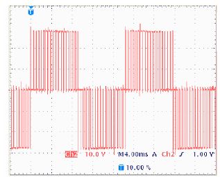
Fig.
3: Output voltage of 5-level inverter at Vdc=50V, and ma=0.8

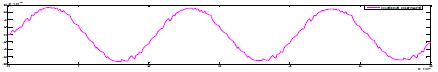
Fig.
4: Load current of 5-level inverter at Vdc=50V, and ma=0.8

Fig. 5: Harmonic spectrum of output
voltage of 5-level inverter at Vdc=50V, and ma=0.8

Fig. 6: Output voltage of 7-level
inverter at Vdc=50V, and ma=0.8

Fig. 7: Load current of 7-level inverter
at Vdc=50V, and ma=0.8

Fig. 8: Harmonic spectrum of output
voltage of 7-level inverter at Vdc=50V, and ma=0.8

Fig. 9: Output voltage of 9-level
inverter at Vdc=50V, and ma=0.8

Fig. 10: Harmonic spectrum of output
voltage of 9-level inverter at Vdc=50V, and ma=0.8
CONCLUSION
A new family of multilevel inverters has
been presented. It has the advantage of its reduced number of switching devices
compared to conventional similar inverters. However, the high rating of its
four main switches limits its usage to the medium voltage range. The modes of operation
and switching strategy of the new topology are presented. A programmed PWM
algorithm based on the theory of resultant has been applied for harmonic elimination
of the new topology. Since the solution algorithm is based on solving
polynomial equations, it has the advantage of finding all existed solutions,
where the solution produces the lowest THD is selected. Other PWM methods and
techniques are also expected to be successively applied to the proposed
topology. The simulation results and experimental results show that the
algorithm can be effectively used to eliminate specific higher order harmonics
of the new topology and results in a dramatic decrease in the output voltage
THD.
REFERENCES
[1] J.S. Lai and F.Z. Peng, “Multileve
Converters – A New Breed of Power Converters”, IEEE Trans. Ind. Appl., Vol. 32,
No.3, 1996, pp. 509-517.
[2] L.M. Tolbert and F.Z. Peng, “Multilevel
Converters as a Utility Interface for Renewable Energy System”, IEEE Proceedings-Power Eng. Soc. Summer Meeting,
Seattle, WA, 2000, pp. 1271-1274.
[3] K. Corzine and Y. Familiant, “A New
Cascaded Multilevel H-Bridge Drive”, IEEE Transactions Power Electron., Vol. 17,
No.1, 2002, pp. 125-131.
[4] X. Yuan and I. Barbi, “Fundamentals of a
New Diode Clamping multilevel Inverter”, IEEE Transactions Power Electron.,
Vol. 15, No.4, 2000, pp. 711-718.
[5] L.M. Tolbert and T.G. Habetler, “Novel
Multilevel Inverter Carrier-Based PWM Methods”, IEEE Trans. Ind. Appl., 35,
1999, pp. 1098-1107.
.