ABSTRACT
This article explores the development of FPGA
based controller for conventional and cascaded multilevel PWM single phase
inverter. The conventional multilevel inverter is constructed by the H-bridge
and cascaded multilevel inverter constructed by two full H-bridges. FPGA logic
device is chosen for the hardware implementation of control circuit. VHDL
language is used to model the inverter switching strategies. The proposed controller
generates 4 and 8 control signals for conventional multilevel inverter and
cascaded multilevel inverter respectively. These inverters provide 3-level and 7-
level output voltages. Matlab/System generator and XILINX are used as a
simulation and compiler architecture of control circuit embedded in FPGA. These
inverter topologies with filters would have reduced harmonics and can operate
at high efficiency.
KEYWORDS:
1.
Field Programmable
gate array (FPGA)
2.
VHDL Hardware
description language
3.
Multilevel
inverter
4.
Cascaded multilevel inverter
5.
Digital
controller.
SOFTWARE: MATLAB/SIMULINK
CIRCUIT
DIAGRAMS:

Fig 1.Conventional multilevel PWM
single phase inverter

Fig 2. Cascade PWM single phase
inverter with a single DC supply source.
EXPECTED SIMULATION RESULTS:

Fig 3. three -level multilevel PWM
single phase inverter output voltage

Fig
4.three-level multilevel PWM single phase inverter output current

Fig
5. order of harmonic measured with respect to the magnitude of the
fundamental frequency for single
phase conventional multilevel VSI

Fig 6.seven -level cascaded PWM
single phase inverter output voltage
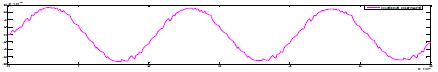
Fig 7. seven-level cascaded PWM
single phase inverter output current

Fig
8.order of harmonic measured with respect to the magnitude of the
fundamental frequency for single
phase Cascaded multilevel VSI
CONCLUSION
The
FPGA based controller switching patterns are adopted and applied to the
multilevel inverter and cascaded multilevel inverter switches to generate
3-level and 7-level output voltages respectively. The FPGA enables to make
easy, fast and flexible design of the control circuit for hardware implementation.
It can effectively extend the modulation index range that facilitates a better
quality output voltage with minimal distortion. The experimental and simulation
results demonstrate quality voltage and current waveform shapes at the output
of the inverter. These inverter topologies with proposed control circuit can be
used for speed control of induction motor and other industrial applications and
would be attempted as a future work.
REFERENCES
[1] .Keith
Corzine and Yakov Familiant “A New Cascaded Multilevel HBridge Drive”- IEEE
Trans on power electronics, Vol.17, no.1, Jan-2002
[2] John N. Chiasson, Burak Özpineci, and Leon M.
Tolbert “A Five-Level Three-Phase Hybrid Cascade Multilevel Inverter Using a
Single DC Source for a PM Synchronous Motor Drive- 2007 IEEE.
[3] Zhong
Du, Burak Ozpineci, and Leon M. Tolbert “Modulation Extension Control of Hybrid
Cascaded H-bridge Multilevel Converters with 7-level Fundamental Frequency
Switching Scheme” Oak Ridge National Laboratory, Oak Ridge
[4] M.I. Ahmad, Z. Husin, R. B. Ahmad, H. A Rahim,
M.S. Abu Hassan, M.N. Md Isa “FPGA based control IC for Multilevel Inverter” Proceedings
of the International Conference on Computer and Communication Engineering 2008
[5] S.
Mekhilef and Masaoud “Xilinx FPGA Based Multilevel PWM Single Phase Inverter”
Engineering e-Transaction, Vol.1, No 2, pp 40-45, 2006