ABSTRACT
This paper proposes a Kalman filter (KF) based H∞ control scheme for a three phase shunt active power
filter (SAPF) system.
For the current control loop, a H∞ controller is designed with a mixed sensitivity approach for achieving
stability and high disturbance
rejection in the SAPF system. A new current reference scheme is also proposed that employs KF to
avoid synchronization circuit and proportional integral
(PI) controller loop
resulting in a reliable and cost-effective SAPF system. This reference scheme can self-regulate the dc-link
voltage by a fast and
adaptive estimation of the source reference current with power system perturbations raised in source or load
sides. The efficacy
of the proposed KF-H∞ control
algorithm is evaluated through
comparison with an existing PI and PI plus vector PI (PI-PIVPI) algorithm and then validated with
experimental studies
pursued using a dSPACE1104. From the obtained experimental results, it is observed that the
proposed SAPF significantly
outperforms the existing PI-PIVPI in terms of exhibiting robustness to modeling uncertainties and
insensitivity to grid
perturbations such as harmonics, measurement noise and phase angle jump. Thus, the power quality
improvement is achieved
in terms of perfect current harmonics cancellation as well as power factor improvement.
KEYWORDS:
1.
Active power
filter
2.
Self-regulate
3.
Robustness
4.
Power quality
5.
Harmonics
cancellation
6.
Power factor improvement
SOFTWARE: MATLAB/SIMULINK
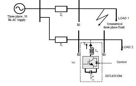
CIRCUIT
DIAGRAM:

Fig.1 Proposed SAPF Control Scheme
EXPECTED SIMULATION RESULTS:

Fig.2
Test Case-1:(a) three-phase supply voltages, (b) three-phase load currents

Fig.3
Test Case-1:(a) three-phase source reference currents in proposed
method,
(b) three-phase compensating currents in proposed method, (c) dclink
voltage
in proposed method

Fig.4.
Test Case-1: Harmonic spectra of (a) phase-a load current, (b) phase a
source
current in the Proposed method, and (c) phase-a source current in the
Existing
method

Fig.5.Test
Case-2: Waveforms of three phase source currents, (i) Proposed
Method,
(ii) Existing Method

Fig.
6. Test Case-2: Harmonic spectra of (a) phase-a source current in
Proposed
Method, and (b) phase-a source current in Existing Method

Fig.7.Test
Case -3: (a) three phase load currents, (b) dc-link voltage in
proposed
method

Fig.
8 Test Case -3: (a) Waveforms of three phase compensating currents,
(b)
Waveforms of three phase source currents , (i) Proposed Method, (ii)
Existing
Method

Fig.
9 Test Case-3: Harmonic spectra of (a) phase-a load current, (b)
phase-a
source current in Proposed Method, and (c) phase-a source current in
Existing
Method

Fig.
10.Test Case-4: (a) Three phase supply voltages, (b) Three phase load
currents,
(c) Three phase compensating currents in Proposed Method

Fig.
11. Case-4: Waveforms of three phase source currents and dc-link
voltage,
(i) Proposed Method, (ii) Existing Method

Fig.
12. Test Case-4: Harmonics spectra of (a) phase-a load current, (b) phasea
source
current in Proposed Method, and (c) phase-a source current in
Existing
Method

Fig.
13. Test Case-5: Harmonics spectra of (a) phase-a load current, (b) phasea
source
current in Proposed Method, and (c) phase-a source current in
Existing
Method
CONCLUSION
In
this paper, a H∞ controller with a new reference current estimation scheme
based on KF has been proposed for a SAPF. This reference generation scheme is
simple yet reliable and self regulator of dc-link voltage without having a PI controller.
Only source current sensors are sufficient to determine the reference current,
which decreases the effective cost of SAPF implementation. Further, H∞ current
controller is designed with a proper selection of weighting functions to specify
the robustness, control effort performance and error tracking performance of
SAPF. Finally, the effectiveness of the proposed KF-H∞ control strategy was
verified through various experimental tests, where the proposed control strategy
presented good steady state as well as dynamic performance against supply or
load variations. Generally power line uncertainties such as fluctuation of load,
variation of system parameter, sudden failure of power system components and
sensor nonlinearities degrade the reliability and efficiency of the SAPF
system. Moreover, grid perturbations such as harmonics, measurement noise and phase
angle jump are responsible for power quality deterioration. Hence, the
objective of designing a robust control strategy in SAPF is achieved by
accommodating all the possible perturbations occurring in the power system. From
the experimental results, it is also observed that the proposed KF-H∞ control
approach to design a SAPF is found to be robust in face parametric
uncertainties due to grid perturbations yielding improvement in power quality
more effectively in terms of tracking error reduction and efficient current
harmonics mitigation.
REFERENCES
[1]
O. Dordevic, M. Jones and E. Levi, ―Analytical
formulas for phase voltage RMS Squared and THD in PWM multiphase systems,‖ IEEE
Trans. on Power Electron., vol. 30, no. 3, pp. 1645-1656, Mar. 2015.
[2]
A. F.
Zobaa, ―Optimal multiobjective design of hybrid active power filters
considering a distorted environment,‖ IEEE Trans. on Ind. Electron., vol.
61, no. 1, pp. 107-113, Jan. 2014.
[3]
X. Hao,
X. Yang and T. Liu, "A sliding-mode controller with multiresonant sliding surface
for single-phase grid connected VSI with an LCL Filter," IEEE Trans. on
Power Electron., vol. 28, no. 5, pp. 2259-2268, May. 2013.
[4]
Q. N. Trinh, and H. H. Lee, ―An advanced current
control strategy for three phase shunt active power filters,‖ IEEE Trans. on
Ind. Electron., vol. 60, no. 12, pp. 5400-5410, Dec. 2013.
[5]
J. F. Petit, G. Robles, and H. Amaris, ―Current
reference control for shunt active power filters under non sinusoidal voltage
conditions, IEEE Trans. on Power Del., vol. 22, no.4, pp. 2254–2261,
Oct. 2007.