asokatechnologies@gmail.com 09347143789/09949240245

Search This Blog

Saturday 12 January 2019

Control of a Three-Phase Hybrid Converter for a PV Charging Station


ABSTRACT:  
Hybrid boost converter (HBC) has been proposed to replace a dc/dc boost converter and a dc/ac converter to reduce conversion stages and switching loss. In this paper, control of a three-phase HBC in a PV charging station is designed and tested. This HBC interfaces a PV system, a dc system with a hybrid plugin electrical vehicles (HPEVs) and a three-phase ac grid. The control of the HBC is designed to realize maximum power point tracking (MPPT) for PV, dc bus voltage regulation, and ac voltage or reactive power regulation. A test bed with power electronics switching details is built in MATLAB/SimPowersystems for validation. Simulation results demonstrate the feasibility of the designed control architecture. Finally, lab experimental testing is conducted to demonstrate HBC’s control performance.
KEYWORDS:
1.      Plug-in hybrid vehicle (PHEV)
2.      Vector Control
3.      Grid-connected Photovoltaic (PV)
4.      Three-phase Hybrid Boost Converter
5.      Maximum Power Point Tracking (MPPT)
6.      Charging Station

SOFTWARE: MATLAB/SIMULINK

 BLOCK DIAGRAM:


Fig. 1. Topology of the three-phase HBC-based PV charging station.


EXPECTED SIMULATION RESULTS:


Fig. 2. Performance of a modified IC-PI MPPT algorithm when solar
irradiance variation is applied.


Fig. 3. Performance of the dc voltage control in the vector control. The solid lines represent the system responses when the dc voltage control is enabled. The dashed lines represent the system responses when the dc voltage control
is disabled.


Fig. 4. Performance of a proposed vector control to supply or absorb reactive power independently.

Fig. 5. Power management of PV charging station.


Fig. 6. Dst, Md and Mq for case 4.

Fig. 
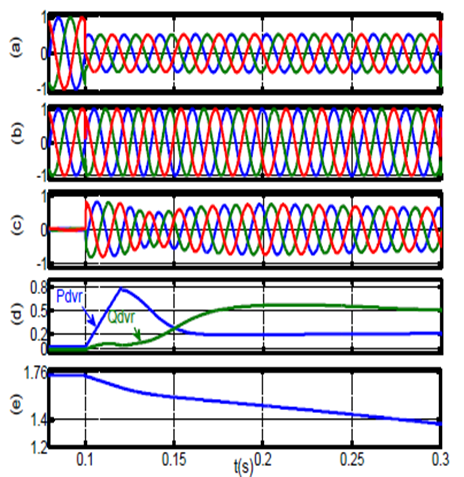
7. System performance under 70% grid’s voltage drop.

CONCLUSION:

Control of three-phase HBC in a PV charging station is proposed in this paper. The three-phase HBC can save switching loss by integration a dc/dc booster and a dc/ac converter converter into a single converter structure. A new control for the three-phase HBC is designed to achieve MPPT, dc voltage regulation and reactive power tracking. The MPPT control utilizes modified incremental conductance-PI based MPPT method. The dc voltage regulation and reactive power tracking are realized using vector control.
Five case studies are conducted in computer simulation to demonstrate the performance of MPPT, dc voltage regulator, reactive power tracking and overall power management of the PV charging station. Experimental results verify the operation of the PHEV charging station using HBC topology. The simulation and experimental results demonstrate the effectiveness and robustness of the proposed control for PV charging station to maintain continuous dc power supply using both PV power and ac grid power.
REFERENCES:
[1] M. Ehsani, Y. Gao, and A. Emadi, Modern electric, hybrid electric, and fuel cell vehicles: fundamentals, theory, and design. CRC press, 2009.
[2] K. Sikes, T. Gross, Z. Lin, J. Sullivan, T. Cleary, and J. Ward, “Plugin hybrid electric vehicle market introduction study: final report,” Oak Ridge National Laboratory (ORNL), Tech. Rep., 2010.
[3] A. Khaligh and S. Dusmez, “Comprehensive topological analysis of conductive and inductive charging solutions for plug-in electric vehicles,” IEEE Transactions on Vehicular Technology, vol. 61, no. 8, pp. 3475– 3489, 2012.
[4] T. Anegawa, “Development of quick charging system for electric vehicle,” Tokyo Electric Power Company, 2010.
[5] F. Musavi, M. Edington, W. Eberle, and W. G. Dunford, “Evaluation and efficiency comparison of front end ac-dc plug-in hybrid charger topologies,” IEEE Transactions on Smart grid, vol. 3, no. 1, pp. 413–421, 2012.

Wednesday 9 January 2019

Design of an Efficient Dynamic Voltage Restorer for Compensating Voltage Sags, Swells, and Phase Jumps


ABSTRACT:  
This paper presents a novel design of a dynamic voltage restorer (DVR) which mitigate voltage sags, swell, and phase jumps by injecting minimum active power in system and provides the constant power at load side without any disturbance. The design of this compensating device presented here includes the combination of PWM-based control scheme, dq0 transformation and PI controller in control part of its circuitry, which enables it to minimize the power rating and to response promptly to voltage quality problems faced by today’s electrical power industries. An immense knowledge of power electronics was applied in order to design and model of a complete test system solely for analyzing and studying the response of this efficient DVR. In order to realize this control scheme of DVR MATLAB/SIMULINK atmosphere was used. The results of proposed design of DVR’s control scheme are compared with the results of existing classical DVR which clearly demonstrate the successful compensation of voltage quality problems by injecting minimum active power.
KEYWORDS:
1.      Dynamic voltage restorer
2.      Voltage sags
3.      Voltage swells
4.      Phase jumps
5.      PWM-based control
6.      DQ0 transformation
7.      PI controller
SOFTWARE: MATLAB/SIMULINK
BLOCK DIAGRAM:


Fig.1. Block Diagram of DVR

 EXPECTED SIMULATION RESULTS:


Fig.2.Source Voltage with Sag of 0.5 p.u.


Fig.3.Load Voltage after Compensation through proposed DVR


Fig.4. Load Voltage after Compensation through classical DVR


Fig.5. Voltage injected by proposed DVR as response of Sag


Fig.6.Source Voltage with Swell of 1.5 p.u.


Fig.7. Load Voltage after compensation through proposed DVR


. Fig.8. Load Voltage after Compensation through classical DVR


Fig.9. Voltage injected by DVR as response of Swell


Fig.10. .Load Voltage after Compensation of Phase jump


Fig.11. dq0 form of difference voltage obtained by proposed DVR


Fig.12.dq0 form of difference voltage obtained by classical DVR


CONCLUSION:

As the world is moving towards modernization, the most essential need that it has is of an efficient and reliable power of excellent quality. Nowadays, more and more sophisticated devices are being introduced, and their sensitivity is dependent upon the quality of input power, even a slight disturbance in power quality, such as Voltage sags, voltage swells, and harmonics, which lasts in tens of milliseconds, can result in a huge loss because of the failure of end use equipments. For catering such voltage quality problems an efficient DVR is proposed in this paper with the capability of mitigating voltage sags, swells, and phase jumps by injecting minimum active power hence decreasing the VA rating of DVR. compensation of voltage quality problems using a comparatively low voltage DC battery and by injecting minimum active power.

 REFERENCES:
[1] Kumar, R. Anil, G. Siva Kumar, B. Kalyan Kumar, and Mahesh K. Mishra. "Compensation of voltage sags and harmonics with phasejumps through DVR with minimum VA rating using Particle Swarm Optimization." In Nature & Biologically Inspired Computing, 2009. NaBIC 2009. World Congress on, pp. 1361-1366. IEEE, 2009.
[2] Songsong, Chen, Wang Jianwei, Gao Wei, and Hu Xiaoguang. "Research and design of dynamic voltage restorer." In Industrial Informatics (INDIN), 2012 10th IEEE International Conference on, pp. 408-412. IEEE, 2012.
[3] A. Bendre, D. Divan, W. Kranz, and W. E. Brumsickle, "Are Voltage Sags Destroying Equipment?," IEEE Industry Applications Magazine, vol. 12, pp. 12-21, July-August 2006.
[4] Nielsen, John Godsk, and Frede Blaabjerg. "A detailed comparison of system topologies for dynamic voltage restorers." Industry Applications, IEEE Transactions on 41, no. 5 (2005): 1272-1280.
[5] Zhou, Hui, Jing Zhou, and Zhi-ping Qi. "Fast voltage detection for a single-phase dynamic voltage restorer (DVR) using morphological low-pass filters." In Electric Utility Deregulation and Restructuring and Power Technologies, 2008. DRPT 2008. Third International Conference on, pp. 2042-2046. IEEE, 2008.

An Enhanced Voltage Sag Compensation Scheme for Dynamic Voltage Restorer


 ABSTRACT:  

 This paper deals with improving the voltage quality of sensitive loads from voltage sags using dynamic voltage restorer (DVR). The higher active power requirement associated with voltage phase jump compensation has caused a substantial rise in size and cost of dc link energy storage system of DVR. The existing control strategies either mitigate the phase jump or improve the utilization of dc link energy by (i) reducing the amplitude of injected voltage, or (ii) optimizing the dc bus energy support. In this paper, an enhanced sag compensation strategy is proposed that mitigates the phase jump in the load voltage while improving the overall sag compensation time. An analytical study shows that the proposed method significantly increases the DVR sag support time (more than 50%) compared with the existing phase jump compensation methods. This enhancement can also be seen as a considerable reduction in dc link capacitor size for new installation. The performance of proposed method is evaluated using simulation study and finally, verified experimentally on a scaled lab prototype.
KEYWORDS:

1.      Dynamic voltage restorer (DVR)
2.      Voltage source inverter (VSI)
3.      Voltage sag compensation
4.      Voltage phase jump compensation
SOFTWARE: MATLAB/SIMULINK

CIRCUIT DIAGRAM:


Fig. 1 Basic DVR based system configuration.

 EXPECTED SIMULATION RESULTS:


Fig. 2. Simulation results for the proposed sag compensation method for 50% sag depth. (a) PCC voltage, (b) load voltage, (c) DVR voltage, (d) DVR active and reactive power, and (e) dc link voltage.


Fig. 3. Simulation results for the proposed sag compensation method for 23% sag depth. (a) PCC voltage, (b) load voltage, (c) DVR voltage, (d) DVR active and reactive power, and (e) dc link voltage.

CONCLUSION:

In this paper an enhanced sag compensation scheme is proposed for capacitor supported DVR. The proposed strategy improves the voltage quality of sensitive loads by protecting them against the grid voltage sags involving the phase jump. It also increases compensation time by operating in minimum active power mode through a controlled transition once the phase jump is compensated. To illustrate the effectiveness of the proposed method an analytical comparison is carried out with the existing phase jump compensation schemes. It is shown that compensation time can be extended from 10 to 25 cycles (considering presag injection as the reference method) for the designed limit of 50% sag depth with 450 phase jump. Further extension in compensation time can be achieved for intermediate sag depths. This extended compensation time can be seen as considerable reduction in dc link capacitor size (for the studied case more than 50%) for the new installation. The effectiveness of the proposed method is evaluated through extensive simulations in MATLAB/Simulink and validated on a scaled lab prototype experimentally. The experimental results demonstrate the feasibility of the proposed phase jump compensation method for practical applications.
REFERENCES:
[1] J.A. Martinez and J.M. Arnedo, “Voltage sag studies in distribution networks- part I: System modeling,” IEEE Trans. Power Del., vol. 21,no. 3, pp. 338–345, Jul. 2006.
[2] J.G. Nielsen, F. Blaabjerg and N. Mohan, “Control strategies for dynamic voltage restorer, compensating voltage sags with phase jump,” in Proc. IEEE APEC, 2001, pp. 1267–1273.
[3] J.D. Li, S.S. Choi, and D.M. Vilathgamuwa, “Impact of voltage phase jump on loads and its mitigation,” in Proc. 4th Int. Power Electron. Motion Control Conf., Xian, China, Aug. 14–16, 2004, vol. 3, pp. 1762– 176.
[4] M. Sullivan, T. Vardell, and M. Johnson, “Power interruption costs to industrial and commercial consumers of electricity, IEEE Trans. Ind App., vol. 33, no. 6, pp. 1448–1458, Nov. 1997.
[5] J. Kaniewski, Z. Fedyczak and G. Benysek "AC Voltage Sag/Swell Compensator Based on Three-Phase Hybrid Transformer With Buck- Boost Matrix-Reactance Chopper", IEEE Trans. Ind. Electron., vol.61, issue. 8, Aug 2014.


Monday 7 January 2019

An Improved Torque and Current Pulsation Suppression Method for Railway Traction Drives Under Fluctuating DC-Link Voltage


ABSTRACT:  
For railway traction drives, the active front end usually adopts a single-phase rectifier. However, the dc-link voltage of this single-phase rectifier contains a second-order fluctuating component due to the fluctuation of the instantaneous power at both the ac and dc sides. Fed by the fluctuating dc-link voltage, the traction motor suffers from severe torque and current pulsation. The hardware solution with an additional LC resonant filter is simple, but it will reduce the power density of the system. An alternative solution is to eliminate the beat component in the stator voltage/current through modulation ratio or frequency compensation. However, it is difficult to achieve high performance for the conventional feedforward method. In this paper, an improved closed-loop torque and current pulsation suppression method is proposed, which can eliminate the q-axis current pulsation component in the field-oriented control system through frequency compensation. The torque pulsation suppression is also achieved automatically. Simulation and experimental results show that the proposed scheme can effectively reduce the torque and current pulsation in various operation modes compared with the conventional feedforward method.
KEYWORDS:
1.      Fluctuating dc-link voltage
2.      q-axis current pulsation
3.      Suppression
4.      Torque pulsation
5.      Traction drive
SOFTWARE: MATLAB/SIMULINK
CIRCUIT DIAGRAM:


Fig. 1. Circuit schematic of the ac/dc/ac traction drive system.
EXPECTED SIMULATION RESULTS:


Fig. 2. Simulation results of two methods in the asynchronous modulation mode. (a) Line voltage of the motor. (b) and (c) Stator current and torque with the conventional method. (d) and (e) Stator current and torque with the proposed method. (f) DC-link voltage of the inverter without and with the proposed method.
(g) Transition waveforms of the stator current without and with the proposed method.


Fig. 3. Spectrum analysis of the simulation results of the two methods in the asynchronous modulation mode. (a)–(c) Stator current without compensation, with the conventional method, and with the proposed method. (d)–(f) Torque without compensation, with the conventional method, and with the proposed method.


Fig. 4. Simulation results of the two methods in the synchronous modulation mode. (a) Line voltage of the motor. (b) and (c) Stator current and torque with the conventional method. (d) (e) Stator current and torque with the proposed method.


Fig. 5. Simulation results of the two methods in the square-wave modulation mode. (a) Line voltage of the motor. (b) and (c) Stator current and torque with the conventional method. (d) and (e) Stator current and torque with the proposed method.
CONCLUSION:

A closed-loop torque and current pulsation suppression method for railway traction drives under fluctuating dc-link voltage is proposed. This method aims to eliminate the q-axis current pulsation component in the FOC system through output frequency compensation. The torque pulsation suppression is achieved on the basis of q-axis current pulsation elimination automatically. A resonant controller is proposed for the closed loop control of q-axis current and dynamic compensation of the output frequency. Different from the conventional feed forward open-loop frequency compensation method, the torque pulsation with the proposed method is suppressed through the elimination of the q-axis current pulsation component rather than the beat component in the output voltage. The effectiveness of the proposed method have been verified by simulation and experiments on traction drives with the inverter operated in asynchronous, synchronous, and square wave modulation modes, respectively. The results have been compared to those with the conventional feed forward frequency compensation method based on fluctuating dc-link voltage detection. Both simulation and experimental results show that the suppression of stator current and torque pulsation are obvious in different modulation modes with the proposed control method using the same dc-link capacitance.
The proposed suppression method can reduce the sensitivity of the system to variations of the grid frequency. However, the fluctuating component in the dc-link voltage will be increased with the proposed method compared with the LC resonant filter solution.
REFERENCES:
[1] R. J. Hill, “Electric railway traction. II. Traction drives with three-phase induction motors,” Power Eng. J., vol. 8, no. 3, pp. 143–152, Jun. 1994.
[2] A. Steimel, “Electric railway traction in Europe,” IEEE Ind. Appl. Mag., vol. 2, no. 6, pp. 6–17, Nov./Dec. 1996.
[3] H. Ouyang, K. Zhang, P. Zhang, Y. Kang, and J. Xiong, “Repetitive compensation of fluctuating DC link voltage for railway traction drives,” IEEE Trans. Power Electron., vol. 26, no. 8, pp. 2160–2171, Aug. 2011.
[4] J. Klima, M. Chomat, and L. Schreier, “Analytical closed-form investigation of PWM inverter induction motor drive performance under DC bus voltage pulsation,” IET Electr. Power Appl., vol. 2, no. 6, pp. 341–352, Nov. 2008.
[5] A. Cheok, S. Kawamoto, T. Matsumoto, and H. Obi, “AC drive with particular reference to traction drives,” in Proc. 4th Int. Conf. Adv. Power Syst. Control, Oper. Manage., 1997, pp. 348–353.