ABSTRACT:
This paper presents a novel design of
a dynamic voltage restorer (DVR) which mitigate voltage sags, swell, and phase
jumps by injecting minimum active power in system and provides the constant
power at load side without any disturbance. The design of this compensating
device presented here includes the combination of PWM-based control scheme, dq0
transformation and PI controller in control part of its circuitry, which
enables it to minimize the power rating and to response promptly to voltage
quality problems faced by today’s electrical power industries. An immense
knowledge of power electronics was applied in order to design and model of a complete
test system solely for analyzing and studying the response of this efficient
DVR. In order to realize this control scheme of DVR MATLAB/SIMULINK atmosphere
was used. The results of proposed design of DVR’s control scheme are compared
with the results of existing classical DVR which clearly demonstrate the
successful compensation of voltage quality problems by injecting minimum active
power.
KEYWORDS:
1.
Dynamic
voltage restorer
2.
Voltage
sags
3.
Voltage
swells
4.
Phase
jumps
5.
PWM-based
control
6.
DQ0
transformation
7.
PI
controller
SOFTWARE: MATLAB/SIMULINK
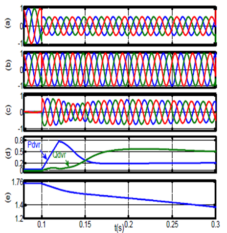
BLOCK DIAGRAM:

Fig.1. Block Diagram of DVR

Fig.2.Source Voltage with Sag of 0.5 p.u.

Fig.3.Load Voltage after Compensation through proposed DVR

Fig.4. Load Voltage after Compensation through classical DVR

Fig.5. Voltage injected by proposed DVR as response of Sag

Fig.6.Source Voltage with Swell of 1.5 p.u.

Fig.7. Load Voltage after compensation through proposed DVR

. Fig.8. Load Voltage after Compensation through classical DVR

Fig.9. Voltage injected by DVR as response of Swell

Fig.10. .Load Voltage after Compensation of Phase jump

Fig.11. dq0 form of difference voltage obtained by proposed DVR

Fig.12.dq0 form of difference voltage obtained by classical DVR
CONCLUSION:
As the world is moving towards modernization, the most essential
need that it has is of an efficient and reliable power of excellent quality. Nowadays,
more and more sophisticated devices are being introduced, and their sensitivity
is dependent upon the quality of input power, even a slight disturbance in
power quality, such as Voltage sags, voltage swells, and harmonics, which lasts
in tens of milliseconds, can result in a huge loss because of the failure of
end use equipments. For catering such voltage quality problems an efficient DVR
is proposed in this paper with the capability of mitigating voltage sags,
swells, and phase jumps by injecting minimum active power hence decreasing the
VA rating of DVR. compensation
of voltage quality problems using a comparatively low voltage DC battery and by
injecting minimum active power.
[1] Kumar, R. Anil, G. Siva Kumar, B. Kalyan Kumar, and Mahesh
K. Mishra. "Compensation of voltage sags and harmonics with phasejumps through
DVR with minimum VA rating using Particle Swarm Optimization." In Nature
& Biologically Inspired Computing, 2009. NaBIC 2009. World Congress on,
pp. 1361-1366. IEEE, 2009.
[2] Songsong, Chen, Wang Jianwei, Gao Wei, and Hu Xiaoguang. "Research
and design of dynamic voltage restorer." In Industrial Informatics
(INDIN), 2012 10th IEEE International Conference on, pp. 408-412. IEEE, 2012.
[3] A. Bendre, D. Divan, W. Kranz, and W. E. Brumsickle,
"Are Voltage Sags Destroying Equipment?," IEEE Industry
Applications Magazine, vol. 12, pp. 12-21, July-August 2006.
[4] Nielsen, John Godsk, and Frede Blaabjerg. "A detailed
comparison of system topologies for dynamic voltage restorers." Industry
Applications, IEEE Transactions on 41, no. 5 (2005): 1272-1280.
[5] Zhou, Hui, Jing Zhou, and Zhi-ping Qi. "Fast voltage
detection for a single-phase dynamic voltage restorer (DVR) using morphological
low-pass filters." In Electric Utility Deregulation and Restructuring and
Power Technologies, 2008. DRPT 2008. Third International Conference on, pp.
2042-2046. IEEE, 2008.