ABSTRACT:
Recently, Asynchronous
Motors are extensively used as workhorse in a multitude of industrial and high
performance applications. Induction Motors (IM) have wide applications in
today’s industry because of their robustness and low maintenance. A smart and
fast speed control system, however, is in most cases a prerequisite for most applications.
This work presents a smart control system for IM using an Adaptive Fuzzy Logic
Controller (AFLC) based on the Levenberg–Marquardt algorithm. A synchronously rotating
reference frame is used to model IM. To achieve maximum efficiency and torque
of the IM, speed control was found to be one of the most challenging issues. Indirect
Field-Oriented Control (IFOC) or Indirect Vector Control techniques with robust
AFLC offer remarkable speed control with high dynamic response. Computer
simulation results using MATLAB/Simulink® Toolbox are described and examined in
this study for conventional PI and AFLC. AFLC presents robustness as regards
overshoot, undershoot, rise time, fall time, and transient oscillation for
speed variation of IFOC IM drive in
comparison with classical PI. Moreover, load disturbance rejection capability
for the designed control scheme is also verified with the AFL controller.
KEYWORDS:
1. Induction Motor (IM)
2. Indirect Field-Oriented Control (IFOC)
3. Pulse Width Modulation
(PWM)
SOFTWARE: MATLAB/SIMULINK
BLOCK DIAGRAM:

Fig. 1 Proposed system
block diagram using AFLC
EXPERIMENTAL RESULTS:

Fig. 2 dq
axis stator currents for
both AFLC & PI controller

Fig. 3 Stator phase
voltage for both AFLC & PI controller

Fig. 4 Stator phase
current for both AFLC & PI controller

Fig. 5 Rotor speed under
variable load torque, a comparison of AFLC based on LM & PI

Fig. 6 dq-axis
stator currents for both AFLC & PI controller
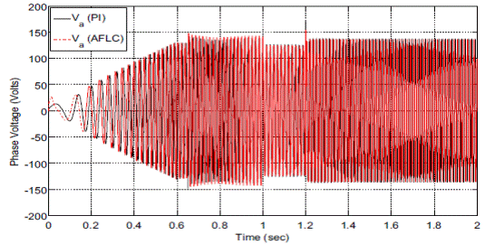
Fig. 7 Stator phase
voltage for both AFLC & PI controller

Fig. 8 Stator phase
current for both AFLC & PI controller

Fig. 9 Rotor speed under
variable load torque, a comparison of AFLC based on LM & PI

Fig. 10 dq-axis
stator currents for both AFLC & PI controller

Fig. 11 Stator phase
voltage for both AFLC & PI controller

Fig. 12 Stator phase
current for both AFLC & PI controller
In this paper, an Indirect
Field-Oriented Control (IFOC) scheme for a drive system of three-phase
induction motor is effectively investigated and validated using various
simulation results in Matlab/Simulink. The performance of proposed controller
is verified by introducing variation in speed and load torque. Simulation
results demonstrate that PI has sluggish response compared to AFLC. In all load
torque variations, the proposed AFLC shows robustness and continues to track
the reference with small steady-state error. Moreover, AFLC based on LM is
robust to model parameter variations, load variations and less sensitive to
uncertainties and disturbances. The proposed scheme verifies superior and
smoother performance with improved dynamic response. Furthermore, the effectiveness of proposed
AFLC is evaluated and justified from performance
indices IAE, ISE and ITAE.
REFERENCES:
1. Leonhard W (1996)
Controlled AC drives, a successful transfer from ideas to industrial practice.
Control Eng Pract 4(7):897–908
2. Fitzgerald
AE,KingsleyCU, StephenD(1990) Electricmachinery, 5th edn. McGraw-Hill, New York
3. Marino R, Peresada S,
Valigi P (1993) Adaptive input-output linearizing control of induction motors. IEEE Trans Autom
Cont 38(2):208–221
4. Leonhard W (1985)
Control of electrical drives. Springer-, Berlin
5. HeinemannG(1989)
Comparison of several control schemes for ac induction motors. In: Proceedings
of European Power Electronics Conference (EPE’89), pp 843–844


