asokatechnologies@gmail.com 09347143789/09949240245

Search This Blog

Monday 20 June 2022

Modeling and Simulation of Impedance Distance Relay for Fault Location and Protection of Single Wire Earth Return Line


ABSTRACT:

Different technologies and resources are utilized to provide electricity access for the rural population around the world. Single wire earth return (SWER) line gets prominent attention around the globe to electrify low load profile customers and remote load like telecom base stations by extending from the nearby medium grid. SWER distribution system is designed by tapping from medium voltage distribution line using an isolation transformer. Unlike other distribution systems, the secondary side of a transformer has an only single line with dedicated perfect grounding system. SWER lines are considered as a cost-effective solution, compared to the three phase grid extension by electric utility companies. Since line route is mostly in rural areas with different geographical topologies, natural and human-made faults are inevitable scenarios on the line. According to a preference of utilities and geographical locations, SWER lines are equipped with over current relay, surge arrestors or reclosers to isolate faulty line during the fault. The two main challenges on SWER line protection are to back up existing over current protection relay when it fails to clear the fault and to locate the location of fault for line maintenance. Technicians patrol up to hundreds of km along SWER line to locate a fault. This activity will be inefficient and time-consuming way of locating the fault. In this paper, we model and simulate the impedance distance relay to back up existing protection system and locate the fault. Our model successfully backs up definite time over current (DTOC) relay for a single line to ground (SLG) faults across the line. Consequently, fault locator-block locates the faulty line position.

 KEYWORDS:

1.      SWER

2.      Rural Electrification

3.      Impedance relay

4.      Fault location

5.      Protection

SOFTWARE: MATLAB/SIMULINK

BLOCK DIAGRAM:


Fig.1.Impedance relay simulation model

 EXPECTED SIMULATION RESULTS:


Fig.2.Fault cleared by DTOC


 Fig.3.Fault cleared by Zone-1 relay


Fig.4.Fault cleared by zone -2 relay


CONCLUSION:

In this paper, the two challenges on SWER line, backup protection of DTOC relay and fault location during fault are addressed. An impedance relay is proposed to backup DTOC relay and to locate faults on SWER line.The simulation is done on MATLAB/SIMULINK on each step of 15km from relay point to the entire line. A fault is simulated at 0.4 s and during the inception of fault, the proposed impedance relay managed to clear the fault according to the intentional time delay set between each zone when DTOC fails to operate. Fault locator-block also measures the fault location by considering fault impedance during a fault. The model can measure a SWER line fault location for a fault impendence of 5Ω and below with less than 3% errors. Whereas, fault impedance compensation is required for a fault impedance greater than 10Ω to achieve better result with minimum error percentage.

 REFERENCES:

[1] P. Cook, "Infrastructure, rural electrification and development," Energy Sustinable Development , pp. 304-313, 2011.

[2] IEA, "Iea.org/sdg/electricity/," IEA, [Online]. Available: https://www.iea.org/sdg/electricity/. [Accessed 10 03 2019].

[3] ESAMP, "Reducing the Cost of Grid Extension for Rural Electrifcation," The International Bank for Reconstruction and Development 227.200, USA, 2000.

[4] L.MANDENO, "RURAL POWER SUPPLY, ESPECIALLY IN BACK COUNTRY AREAS.," in Proceedings of the New Zealand Institution of Engineers, Vol. 33 (1947), 1947.

[5] P. Grad, "Energy Source & Distribution," 2014, 18 May 2014. Available: https://www.esdnews.com.au/swer-still-going-strong/. [Online] [Accessed 11 March 2019].

Transmission Line Protection with Distance Relay


ABSTRACT:

 With the development in science and engineering the power system protection field also get advanced which includes the development of relays .the relays journey started by electromechanical then solid state and now digital and numerical relays .An economical and feasible solution to investigate the performance of relays and protection system offered by modeling of protective relays .Distance relay is one of the effective protective relays that are used for the protection of extra high voltage transmission lines. Distance relays are considered of the high speed class and can provide protection. To detect the fault on transmission lines many distance relays are used but for long transmission line mho relay is most suited. The proposed work is about designing of numerical mho relay in MATLAB / SIMULINK to be used for distance protection schemes of long distance transmission lines with better result and characteristics. The required mho relay algorithm is evaluated by using MATLAB to model the power system under different fault condition and simulate it by using phasor based method available in MATLAB simulation. Thus the modeling and simulation of numerical mho relay gives the improved result and greatly enhance the performance of mho relay

KEYWORDS:

1.      Distance protection

2.      Numerical relays

3.      Matlab/Simulink

SOFTWARE: MATLAB/SIMULINK 

BLOCK DIAGRAM:


EXPECTED  SIMULATION RESULTS:


CONCLUSION:

 This work presents a detailed phasor model for a distance relay of mho characteristics. Mho relays are inherently directional so there is no need for directional elements in the relay model. Here the developed simulation is evaluated for line to line fault on the system, and the results found as Simulation results of different faults regarding type and position show clearly the accurate performance of the developed distance relay model. From results it is seen that speed of operation of numerical mho relay is faster than impedance relay. The model versatility, adaptability and applicability promote it for use in power system simulators. Also, it can be used as a training tool to help users understand how a distance relay works and how settings are performed.

REFERENCES:

I. P.G. Mclaren SM, G.W. Swift SM, 2. Zhang, E. Dirks, R.P. Jayasinghe, I. Fernandouniversity Of Manitoba, Winnipeg, Manitoba, Canada, R3T 2N2.” A New Directional Element For Numerical Distance Relays” IEEE Transactions On Power Delivery, Vol. 10, No. 2, April 1995.

II. P. G. Mclaren, K. Mustaphi, G. Benmouyal, S. Chano, A. Girgis, C. Henville, M. Kezunovic, L. Kojovic, R. Marttila, M. Meisinger, G. Michel, M. S. Sachdev, V. Skendzic, T. S. Sidhu, And D. Tziouvaras” Software Models For Relays” IEEE Transactions On  Power Delivery, VOL. 16, NO. 2, APRIL 2001.

III. Shailendra Kumar Saroj, Harish Balaga, D. N. Viswakarma (Banaras Hindu University), Varanasi, India ” Discrete Wavelet Transform Based Numerical Protection Of Transmission Line ”, Department Of Electrical Engineering Indian Institute Of Technology

IV. Li-Cheng Wu, Chih-Wen Liu, Ching-Shan Chen,Member, National Taiwan University, Taipei, Taiwa, “Modeling And Testing Ofa Digital Distance Relay Using MATLAB / SIMULINK ,IEEE Transaction On Power Delivery,2005.

V. Eng. Abdlmnam A. Abdlrahem , Dr.Hamid H Sherwali Modelling Of Numerical Distance Relays Using Matlab ”, “IEEE Symposium On Industrial Electronics And Applications”,Octobe,2009.


Implementation and Evaluation a SIMULINK Model of a Distance Relay in MATLAB/SIMULINK


 ABSTRACT:

This paper describes the opportunity of implementing a model of a Mho type distance relay with a three zones by using MATLAB/SIMULINK package. SimPowerSystem toolbox was used for detailed modeling of distance relay, transmission line and fault simulation. The proposed model was verified under different tests, such as fault detection which includes single line to ground (SLG) fault, double line fault (LL), double line to ground fault (LLG) and three phase fault, all types of faults were applied at different locations to test this model. Also the Mho R- jX plain was created inside this model to show the trajectory of measured apparent impedance by the relay. The results show that the relay operates correctly under different locations for each fault type. The difficulties in understanding distance relay can be cleared by using MATLAB/SIMULINK software.

KEYWORDS:

1.      Power system protection

2.      Distance relay

3.      Line protection

4.      MATLAB/SIMULINK

5.      Apparent Impedance

SOFTWARE: MATLAB/SIMULINK

BLOCK DIAGRAM:


Figure 1. Overall simulation model

CONCLUSION:

 A Mho type distance relay was successfully developed based on MATLAB/SIMULINK package, (each part of the relay is implemented as a separate function). Each function has been created using special blocks of SIMULINK. By testing the behavior of the developed relay model under different fault conditions, the relay model was able to recognize the appropriate fault type. From perspective impedance calculations, the relay model has the ability of indicating the correct zone of operation in all cases. The relay identifiers the fault locations as expected, as the fault location is changed, the measured impedance change consequently. The impedance path which reflects the behavior of the model under different fault conditions was presented and discussed

REFERENCES:

[1] Anderson. P.M.”Power System Protection”, ISBN 0-07-134323-7 McGraw-Hill,1999.

[2] Muhd Hafizi Idris, Mohd Saufi Ahmad, Ahmad Zaidi Abdullah, Surya Hardi “Adaptive Mho Type Distance Relaying Scheme with Fault Resistance Compensation” 2013 IEEE 7th International Power Engineering and Optimization Conference (PEOCO2013), Langkawi, June 2013.

[3] M. H. Idris, S. Hardi and M. Z. Hassan, “Teaching Distance Relay Using Matlab/Simulink Graphical User Interface”, Malaysian Technical Universities Conference on Engineering and Technology,

November 2012.

[4] L. C. Wu, C. W. Liu and C. S. Chen, “Modeling and testing of a digital distance relay using Matlab/Simulink”, IEEE 2005.

[5] The Math Works, Inc., “SimPowerSystems user‟s guide”, Version 4.6, 2008.


Thursday 3 March 2022

Integration of PV, Battery and Super capacitor in Islanded Microgrid

 ABSTRACT:

Nowadays battery is used to stabilize the DC bus voltage but battery has low power density and high energy density. Whereas the supercapacitor has high power density but low energy density. So, for high energy and power density the integration of battery and supercapacitor is more efficient. It is more challenging to integrate the different sources. So it is required a control strategy to integrate the battery and supercapacitor and provide continuous power to the load. It has also shown that the battery and supercapacitor charged in access mode of power and discharged in deficit mode of power. In this paper proposed a new approach to control the power and dc bus voltage.

 KEYWORDS:

1.      Battery

2.      MPPT Controller

3.      Photo Voltaic Cell

4.      Super capacitor

 SOFTWARE: MATLAB/SIMULINK

 BLOCK DIAGRAM:


Fig.1. Hybrid system model of PV, Battery and Super capacitor

EXPECTED SIMULATION RESULTS:


Fig.2. DC Bus voltages across two terminals using conventional controller


Fig.3. DC Bus voltages across two terminals using proposed controller


Fig.4. Power consumed by the load using conventional controller


Fig.5. Power consumed by the load using proposed controller


Fig.6. Power sharing between different sources using conventional Controller


Fig.7. Power sharing between different sources using proposed controller


Fig.8. SOC of Battery


Fig.9. Battery Voltage


Fig.10. Battery Current


Fig.11. SOC of Super capacitor


Fig.12. Voltage of Super capacitor


Fig.13. Current of Super capacitor


 CONCLUSION:

 In this paper proposed controller is used for proper sharing of power between different energy sources. Here LPF is used to differentiate between the average power supplied by battery and transient power supplied by super capacitor. Now, new scheme of converter is able to deal with fluctuation of voltage. The constant power and constant voltage across load were observed.

REFERENCES:

 [1] U. Manandhar et al., “Energy management and control for grid connected hybrid energy storage system under different operating modes,” IEEE Trans. Smart Grid, vol. 10, no. 2, pp. 1626–1636  2019.

[2] B. H. Nguyen, R. German, J. P. F. Trovao, and A. Bouscayrol, “Real-time energy management of battery/supercapacitor electric vehicles based on an adaptation of pontryagin’s minimum principle,” IEEE Trans. Veh. Technol., vol. 68, no. 1, pp. 203–212, 2019.

[3] Z. Cabrane, M. Ouassaid, and M. Maaroufi, “Battery and supercapacitor for photovoltaic energy storage: A fuzzy logic management,” IET Renew. Power Gener., vol. 11, no. 8, pp. 1157– 1165, 2017.

[4] H. R. Pota, M. J. Hossain, M. A. Mahmud, and R. Gadh, “Control for microgrids with inverter connected renewable energy resources,” IEEE Power Energy Soc. Gen. Meet., vol. 2014-October, no. October, pp. 27–31, 2014.

[5] S. Angalaeswari, O. V. G. Swathika, V. Ananthakrishnan, J. L. F. Daya, and K. Jamuna, “Efficient Power Management of Grid operated MicroGrid Using Fuzzy Logic Controller (FLC),” Energy Procedia, vol. 117, pp. 268–274, 2017.

Induction motor drive for PV water pumping with reduced sensors

ABSTRACT:

This study presents the reduced sensors based standalone solar photovoltaic (PV) energised water pumping. The system is configured to reduce both cost and complexity with simultaneous assurance of optimum power utilisation of PV array. The proposed system consists of an induction motor-operated water pump, controlled by modified direct torque control. The PV array is connected to the DC link through a DC–DC boost converter to provide maximum power point tracking (MPPT) control and DC-link voltage is maintained by a three-phase voltage-source inverter. The estimation of motor speed eliminates the use of tacho generator/encoder and makes the system cheaper and robust. Moreover, an attempt is made to reduce the number of current sensors and voltage sensors in the system. The proposed system constitutes only one current sensor and only one voltage sensor used for MPPT as well as for the phase voltage estimation and for the phase currents’ reconstruction. Parameters adaptation makes the system stable and insensitive toward parameters variation. Both simulation and experimental results on the developed prototype in the laboratory validate the suitability of proposed system.

 SOFTWARE: MATLAB/SIMULINK

 BLOCK DIAGRAM:


Fig. 1
Block diagram

(a)     Conventional system, (b) Proposed system, (c) Scheme of the proposed system

 EXPECTED SIMULATION RESULTS:


Fig. 2 Performance indices

(a) PV array during starting to steady state at 1000 W/m2, (b) IMD indices at 1000 W/m2

 CONCLUSION:

 The modelling and simulation of the proposed system has been carried out in MATLAB/Simulink and its suitability is validated experimentally on a developed prototype in the laboratory. The system comprises of one voltage sensor and one current sensor, which are sufficient for the proper operation of the proposed system. The motor-drive system performs satisfactorily during starting at various insolations, steady-state, dynamic conditions represented by changing insolation. The speed estimation has been carried out by flux components in stationary frame of reference. The flux and torque are controlled separately. Therefore, successful observation of the proposed system with satisfactory performance has been achieved without the mechanical sensors. This topology improves the stability of the system. The stability of the system at rated condition toward stator resistance variation is shown by Nyquist stability curve and the stability toward the rotor-time constant perturbation is shown by Popov's criteria. The DTC of an induction motor with fixed frequency switching technique reduces the torque ripple. The line voltages are estimated from this DC-link voltage. Moreover, the reconstruction of three-phase stator currents has been successfully carried out from DC-link current. Simulation results are well validated by test results. Owing to the virtues of simple structure, control, cost-effectiveness, fairly good efficiency and compactness, it is inferred that the suitability of the system can be judged by deploying it in the field.

REFERENCES:

 [1] Masters, G.M.: ‘Renewable and efficient electric power systems’ (IEEE Press, Wiley and Sons, Inc., Hoboken, New Jersey, 2013), pp. 445–452

[2] Foster, R., Ghassemi, M., Cota, M.: ‘Solar energy: renewable energy and the environment’ (CRC Press, Taylor and Francis Group, Inc., Boca Raton, Florida, 2010)

[3] Parvathy, S., Vivek, A.: ‘A photovoltaic water pumping system with high efficiency and high lifetime’. Int. Conf. Advancements in Power and Energy (TAP Energy), Kollam, India, 24–26 June 2015, pp. 489–493

[4] Shafiullah, G.M., Amanullah, M.T., Shawkat Ali, A.B.M., et al.: ‘Smart grids: opportunities, developments and trends’ (Springer, London, UK, 2013)

[5] Sontake, V.C., Kalamkar, V.R.: ‘Solar photovoltaic water pumping system – a comprehensive review’, Renew. Sustain. Energy Rev., 2016, 59, pp. 1038– 1067

Improved MPPT method to increase accuracy and speed in photovoltaic systems under variable atmospheric conditions

 ABSTRACT:

The changes in temperature and radiation cause visible fluctuations in the output power produced by the photovoltaic (PV) panels. It is essential to keep the output voltage of the PV panel at the maximum power point (MPP) under varying temperature and radiation conditions. In this study, a maximum power point tracking (MPPT) method has been developed which is based on mainly two parts: the first part is adapting calculation block for the reference voltage point of MPPT and the second one is Fuzzy Logic Controller (FLC) block to adjust the duty cycle of PWM applied switch (MOSFET) of the DC-DC converter. In order to evaluate the robustness of the proposed method, Matlab/Simulink program has been used to compare with the traditional methods which are Perturb & Observe (P&O), Incremental Conductance (Inc. Cond.) and FLC methods under variable atmospheric conditions. When the test results are observed, it is clearly obtained that the proposed MPPT method provides an increase in the tracking capability of MPP and at the same time reduced steady state oscillations. The accuracy of the proposed method is between 99.5% and 99.9%. In addition, the time to capture MPP is 0.021 sec. It is about four times faster than P&O and five times faster than for Inc. Cond. and, furthermore, the proposed method has been compared with the conventional FLC method and it has been observed that the proposed method is faster about 28% and also its efficiency is about 1% better than FLC method.

KEYWORDS:

1.      PV

2.      MPPT methods

3.      FLC based MPPT

4.      DC-DC converter

SOFTWARE: MATLAB/SIMULINK

BLOCK DIAGRAM:


Fig. 1. Block diagram of the designed system.

 EXPECTED SIMULATION RESULTS:


Fig. 2. PV currents for proposed MPPT technique.


Fig. 3. PV voltages for proposed MPPT technique under variable irradiance (fixed temperature).


Fig. 4. PV power for four different MPPT techniques under variable temperature (fixed irradiance).


Fig. 5. PV currents for proposed MPPT technique.


Fig. 6. PV voltages for proposed MPPT technique under variable temperature (fixed irradiance).


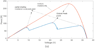
Fig. 7. (a) P-V characteristics curve, (b) Tracking global peak point for proposed MPPT technique.

CONCLUSION:


This study proposes a novel MPPT method and the detailed performance comparison with commonly used methods such as P&O, Incremental conductance and FLC techniques is achieved. Under sudden change in atmospheric operating conditions, the proposed MPPT method performs better performance than other methods to determine MPP. The efficiency of proposed MPPT method is between 99.5% and 99.9%, while P&O is between 91% and 98%, Inc. Cond. Is between 96% and 99% and FLC is between 98.8% and 99.4% for all case studies. The proposed MPPT method has achieved the lowest oscillation rate at the MPP compared to commonly used methods. This brings the method to the forefront in terms of efficiency. The duration of the proposed MPPT technique to reach a steady state has been measured as 0.021 sec. It is about four times faster than P&O and five times faster than for Inc. Cond. and, furthermore, the proposed method has been compared with the conventional FLC method and it has been observed that the proposed method is faster about 28% than FLC method this means the speed of proposed MPPT technique is the best. At the same time, the amount of oscillation is very low compared to conventional methods. The accuracy of the algorithm is high (%99.9 in many study cases) and also the proposed method is easy to implement in the system.

REFERENCES:

[1] Luo HY, Wen HQ, Li XS, Jiang L, Hu YH. Synchronous buck converter based lowcost and high-efficiency sub-module DMPPT PV system under partial shading conditions. Energy Convers Manage 2016;126:473–87.

[2] Babaa SE, Armstrong M, Pickert V. Overview of maximum power point tracking control methods for PV systems. J Power Energy Eng 2014;2:59–72.

[3] Dolara AFR, Leva S. Energy comparison of seven MPPT techniques for PV systems. J Electromagn Anal Appl 2009;3:152–62.

[4] Ngan MS, Tan CW. A study of maximum power point tracking algorithms for standalone photovoltaic systems. Applied Power Electronics Colloquium (IAPEC): IEEE. 2011. p. 22–7.

[5] Liu JZ, Meng HM, Hu Y, Lin ZW, Wang W. A novel MPPT method for enhancing energy conversion efficiency taking power smoothing into account. Energy Convers Manage 2015;101:738–48.