asokatechnologies@gmail.com 09347143789/09949240245

Search This Blog

Friday, 21 November 2014

A Fast Space-Vector Modulation Algorithm for Multilevel Three-Phase Converters

A Fast Space-Vector Modulation Algorithm for
Multilevel Three-Phase Converters

ABSTRACT:

This paper introduces a general space-vector modulation algorithm for -level three-phase converters. The algorithm is computationally extremely efficient and is independent of the number of converter levels. At the same time, it provides good insight into the operation of multilevel converters.

KEYWORDS:

1.      Digital control
2.       Pulse width modulation
3.       Space vectors

SOFTWARE: MATLAB/SIMULINK

 BLOCK DIAGRAM:


Fig.1.Types of multilevel converters.


Fig .2.Classification of multilevel modulations.

  CONCLUSION:

This paper has presented a fast new SVM algorithm for multilevel three-phase converters. The algorithm is general and applicable to converters with any number of levels. In addition, the number of steps required to select the nearest three vectors and compute their duty cycles remains the same regardless of the number of converter levels or the location of the reference vector. In addition, the computational efficiency of this algorithm makes it a useful simulation tool for further study of the properties of multilevel converters.

REFERENCES:

[1] L. M. Tolbert and F. Z. Peng, “Multilevel converters for large electric drives,” in Proc. IEEE APEC’98, vol. 2, 1998, pp. 530–536.
[2] Y. Chen, B. Mwinyiwiwa, Z. Wolanski, and B.-T. Ooi, “Regulating and equalizing dc capacitance voltages in multilevel statcom,” IEEE Trans. Power Delivery, vol. 12, pp. 901–907, Apr. 1997.
[3] J.-S. Lai and F. Z. Peng, “Multilevel converters—A new breed of power converters,” IEEE Trans. Ind. Applicat., vol. 32, pp. 509–517, May/June 1996.
[4] P. M. Bhagwat and V. R. Stefanovic, “Generalized structure of a multilevel PWM inverter,” IEEE Trans. Ind. Applicat., vol. IA-19, pp. 1057–1069, Nov./Dec. 1983.
[5] G. Sinha and T. A. Lipo, “A four level rectifier-inverter system for drive applications,” IEEE Trans. Ind. Applicat., vol. 30, pp. 938–944, July/Aug. 1994.


Simplified SVPWM Algorithm for Neutral Point Clamped 3-level Inverter fed DTC-IM Drive

Simplified SVPWM Algorithm for Neutral Point Clamped 3-level Inverter fed DTC-IM Drive


ABSTRACT:

In this paper, a simplified space vector pulse width modulation (SVPWM) method has been developed for three phase three-level voltage source inverter fed to direct torque controlled (DTC) induction motor drive. The space vector diagram of three-level inverter is simplified into two-level inverter. So the selection of switching sequences is done as conventional two-level SVPWM method.Where in conventional direct torque control (CDTC), the stator flux and torque are directly controlled by the selection of optimal switching modes. The selection is made to restrict the flux and torque errors in corresponding hysteresis bands. In spite of its fast torque response, it has more flux, torque and current ripples in steady state. To overcome the ripples in steady state, a space vector based pulse width modulation (SVPWM) methodology is proposed in this paper. The proposed SVPWM method reduces the computational burden and reduces the total harmonic distortion compared with 2-level one and the conventional one also. To strengthen the voice simulation is carried out and the corresponding results are presented.

KEYWORDS:

1.      SVPWM
2.       DTC

SOFTWARE: MATLAB/SIMULINK

BLOCK DIAGRAM:

Fig.1.Block diagram of proposed DTC drive.

CONCLUSION:

In this paper, a simplified SVPWM algorithm is presented for three-phase three-level inverter fed DTC drive. The proposed algorithm generates the switching pulses similar to a two-level inverter based SVPWM algorithm. Thus, the proposed algorithm reduces the complexity involved in the existing PWM algorithms. To validate the proposed PWM algorithm, numerical simulation studies have been carried out and results are presented. From the simulation results, it can be concluded that the three-level inverter fed DTC drive gives reduced steady state ripples and harmonic distortion.

REFERENCES:

 [1] F. Blaschke “The principle of field orientation as applied to the new transvector closed loop control system for rotating-field machines," Siemens Review, 1972, pp 217-220.
[2] Isao Takahashi and Toshihiko Noguchi, “A new quick-response and high-efficiency control strategy of an induction motor,” IEEE Trans. Ind. Applicat., vol. IA-22, no.5, Sep/Oct 1986, pp. 820-827.
[3] Domenico Casadei, Francesco Profumo, Giovanni Serra, and Angelo Tani, “FOC and DTC: Two Viable Schemes for Induction Motors Torque Control” IEEE Trans. Power Electron., vol. 17, no.5, Sep, 2002, pp. 779-787.
[4] D. Casadei, G. Serra and A. Tani, “Implementation of a direct torque control algorithm for induction motors based on discrete space vector modulation” IEEE Trans. Power Electron., vol.15, no.4, Jul 2000, pp.769-777.

[5] Nabae, A., Takahashi, I., and Akagi, H, "A neutral-point clamped PWM inverter’, IEEE-Trans. Ind. Appl., 1981, 17, (5), pp.518-523.

Thursday, 20 November 2014

Coordinated Control and Energy Management of Distributed Generation Inverters in a Microgrid

Coordinated Control and Energy Management of
Distributed Generation Inverters in a Microgrid

ABSTRACT:

This paper presents a microgrid consisting of different distributed generation (DG) units that are connected to the distribution grid. An energy-management algorithm is implemented to coordinate the operations of the different DG units in the microgrid for grid-connected and islanded operations. The proposed microgrid consists of a photovoltaic (PV) array which functions as the primary generation unit of the microgrid and a proton-exchange membrane fuel cell to supplement the variability in the power generated by the PV array. A lithium-ion storage battery is incorporated into the microgrid to mitigate peak demands during grid-connected operation and to compensate for any shortage in the generated power during islanded operation. The control design for the DG inverters employs a new model predictive control algorithm which enables faster computational time for large power systems by optimizing the steady-state and the transient control problems separately. The design concept is verified through various test scenarios to demonstrate the operational capability of the proposed microgrid, and the obtained results are discussed.

KEYWORDS:
1.      Distributed generation (DG)
2.      Energy management
3.      Micro grid
4.       Model predictive control (MPC).

SOFTWARE: MATLAB/SIMULINK

BLOCK DIAGRAM:


                           Fig. 1. Overall configuration of the proposed microgrid architecture.


 CONCLUSION:

In this paper, a control system that coordinates the operation of multiple DG inverters in a microgrid for grid-connected and islanded operations has been presented. The proposed controller for the DG inverters is based on a newly developed MPC algorithm which decomposes the control problem into steady-state and transient sub problems in order to reduce the overall computation time. The controller also integrates Kalman filters into the control design to extract the harmonic spectra of the load currents and to generate the necessary references for the controller. The DG inverters can compensate for load harmonic currents in a similar way as conventional compensators, such as active and passive filters, and, hence, no additional equipment is required for power-quality improvement. To realize the smart grid concept, various energy-management functions, such as peak shaving and load shedding, have also been demonstrated in the simulation studies. The results have validated that the microgrid is able to handle different operating conditions effectively during grid-connected and islanded operations, thus increasing the overall reliability and stability of the microgrid.

REFERENCES:
[1] S. Braithwait, “Behaviormanagement,” IEEE Power and EnergyMag., vol. 8, no. 3, pp. 36–45, May/Jun. 2010.
[2] N. Jenkins, J. Ekanayake, and G. Strbac, Distributed Generation. London, U.K.: IET, 2009.
[3] M. Y. Zhai, “Transmission characteristics of low-voltage distribution networks in China under the smart grids environment,” IEEE Trans. Power Del., vol. 26, no. 1, pp. 173–180, Jan. 2011.
[4] G. C. Heffner, C. A. Goldman, and M. M. Moezzi, “Innovative approaches to verifying demand response of water heater load control,” IEEE Trans. Power Del., vol. 21, no. 1, pp. 1538–1551, Jan. 2006.
[5] R. Lasseter, J. Eto, B. Schenkman, J. Stevens, H. Vollkommer, D. Klapp, E. Linton, H. Hurtado, and J. Roy, “Certs microgrid laboratory test bed, and smart loads,” IEEE Trans. Power Del., vol. 26, no. 1, pp. 325–332, Jan. 2011.
[6] A. Molderink, V. Bakker, M. G. C. Bosman, J. L. Hurink, and G. J. M. Smit, “Management and control of domestic smart grid technology,” IEEE Trans. Smart Grid, vol. 1, no. 2, pp. 109–119, Sep. 2010.
[7] A. Mohsenian-Rad, V. W. S.Wong, J. Jatskevich, R. Schober, and A. Leon-Garcia, “Autonomous demand-side management based on gametheoretic energy consumption scheduling for the future smart grid,” IEEE Trans. Smart Grid, vol. 1, no. 3, pp. 320–331, Dec. 2010.


Paper Writing for BTech, MTech, PHD for EEE,Power Electronics and Power Systems

Asoka Technologies
Research and Development Centre 

     ACADEMIC MATLAB SIMULATION 2013/14/15 PROJECTS FOR
·       ELECTRICAL AND ELECTRONICs ENGINEERING[EEE]
·       POWER ELECTRONICs AND DRIVES[PED]
·       POWER SYSTEMS[PS].
We Can also Develop Your Own Ideas and Your IEEE Papers With Extension also
We also write papers for your projects and give guidance for paper publishing.
 For Further Details Call Us @
 0-9347143789/9949240245
Visit us at: www.asokatechnologies.in
 For Abstracts of IEEE papers and Any Queries

Wednesday, 19 November 2014

Voltage unbalance and harmonics compensation for islanded microgrid inverters

Voltage unbalance and harmonics compensation for
islanded microgrid inverters

ABSTRACT:

Voltage source inverters (VSIs) are usually used for all kinds of distributed generation interfaces in a microgrid. It is the microgrid’s superiority to power the local loads continuously when the utility fails. When in islanded mode, the voltage and frequency of the microgrid are determined by the VSIs; therefore the power quality can be deteriorated under unbalanced and non-linear loads. A voltage unbalance and harmonics compensation strategy for the VSIs in islanded microgrid is proposed in this study. This method is implemented in a single synchronous reference frame (SRF) and is responsible for both the voltage unbalance and harmonic compensation. Furthermore, the virtual impedance loop is modified to improve the compensation
effect. The impedance model of the VSI is built to explain the compensation ability of the proposed strategy. The whole control system mainly includes power droop controllers, a modified virtual impedance loop and inner SRF-based voltage unbalance and harmonics compensators. The proposed strategy is demonstrated in detail and validated with simulations and experiments.

SOFTWARE: MATLAB/SIMULINK

 BLOCK DIAGRAM:


                Fig. 1 Schematic and control of DGs interface in an AC microgrid
                                a Typical AC microgrid structure with DGs and loads
                                b Schematic of a VSI as the DG interface
                                 c Power droop control loop of DGs interface


CONCLUSION:

This paper proposes a FPS SRF-based control strategy for voltage unbalance and harmonic compensation of the VSIs used as interfaces in islanded microgrid. The voltage compensation loops are integrated within the power droop loops and the virtual output impedance loop. The proposed strategy is implemented in a single SRF with a PI controller for the voltage’s fundamental component regulation and multi-resonant controller for voltage unbalance and selected harmonics compensation. The impedance model of the DG interface inverter is built when controlled by three different control methods to explain the compensation ability of the proposed strategy, which are the conventional PI voltage controller, the PI plus multi-resonant voltage controller and the PI plus multi-resonant voltage controller with modified virtual impedance loop. The simulation and experimental results of the three different control strategies with balanced load, unbalanced load and diode bridge rectifier load are given to validate the effectiveness of the proposed control strategy.


REFERENCES:

1 Lasseter, R.H.: ‘Certs microgrid’. IEEE Int. Conf. System of Systems Engineering, 2007 (SoSE ’07), 2007, pp. 1–5
2 Lasseter, R.H., Piagi, P.: ‘Extended microgrid using (DER) distributed energy resources’. IEEE Power Engineering Society General Meeting, 2007, pp. 1–5
3 Rocabert, J., Luna, A., Blaabjerg, F., Rodri, X., Guez, P.: ‘Control of power converters in AC microgrids’, IEEE Trans. Power Electron., 2012, 27, (11), pp. 4734–4749
4 Ming, H., Haibing, H., Yan, X., Guerrero, J.M.: ‘Multilayer control for inverters in parallel operation without intercommunications’, IEEE Trans. Power Electron., 2012, 27, (8), pp. 3651–3663
5 Guerrero, J.M., Blaabjerg, F., Zhelev, T., et al.: ‘Distributed generation: toward a new energy paradigm’, IEEE. Ind. Electron. Mag., 2010, 4, (1), pp. 52–64


Tuesday, 18 November 2014

Control of Reduced-Rating Dynamic Voltage Restorer with a Battery Energy Storage System

Control of Reduced-Rating Dynamic Voltage Restorer with a Battery Energy Storage System

ABSTRACT:

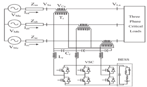
In this paper, different voltage injection schemes for dynamic voltage restorers (DVRs) are analyzed with particular focus on a new method used to minimize the rating of the voltage source converter (VSC) used in DVR. A new control technique is proposed to control the capacitor-supported DVR. The control of a DVR is demonstrated with a reduced-rating VSC. The reference load voltage is estimated using the unit vectors. The synchronous reference frame theory is used for the conversion of voltages from rotating vectors to the stationary frame. The compensation of the voltage sag, swell, and harmonics is demonstrated using a reduced-rating DVR.

KEYWORDS:

1.      Dynamic voltage restorer (DVR)
2.       Power quality
3.      Unit vector
4.      Voltage harmonics
5.       Voltage sag
6.       Voltage swell

SOFTWARE: MATLAB/SIMULINK

BLOCK DIAGRAM:


Fig.1. Schematic of the DVR-connected system.

CONCLUSION:

The operation of a DVR has been demonstrated with a new control technique using various voltage injection schemes. A comparison of the performance of the DVR with different schemes has been performed with a reduced-rating VSC, including a capacitor-supported DVR. The reference load voltage has been estimated using the method of unit vectors, and the control of DVR has been achieved, which minimizes the error of voltage injection. The SRF theory has been used for estimating the reference DVR voltages. It is concluded that the voltage injection in-phase with the PCC voltage results in minimum rating of DVR but at the cost of an energy source at its dc bus.

REFERENCES:

[1] M. H. J. Bollen, Understanding Power Quality Problems—Voltage Sags and Interruptions. New York, NY, USA: IEEE Press, 2000.
[2] A. Ghosh and G. Ledwich, Power Quality Enhancement Using Custom Power Devices. London, U.K.: Kluwer, 2002.
[3] M. H. J. Bollen and I. Gu, Signal Processing of Power Quality Disturbances. Hoboken, NJ, USA: Wiley-IEEE Press, 2006.
[4] R. C. Dugan, M. F. McGranaghan, and H. W. Beaty, Electric Power Systems Quality, 2nd ed. New York, NY, USA: McGraw-Hill, 2006.
[5] A. Moreno-Munoz, Power Quality: Mitigation Technologies in a Distributed Environment. London, U.K.: Springer-Verlag, 2007.


Inner Control Method and Frequency Regulation of a DFIG Connected to a DC Link

Inner Control Method and Frequency Regulation of a DFIG Connected to a DC Link


ABSTRACT:

In this paper, an inner loop for the control and frequency regulation of the doubly fed induction generator connected to a dc link through a diode bridge on the stator is presented. In this system, the stator is directly connected to the dc link using a diode bridge, and the rotor is fed by only a pulse width-modulated (PWM) converter. If compared to the DFIG connected to an ac grid, this system uses one PWM inverter less and a much less expensive diode bridge. Thus, the cost of power electronics is reduced. The application in mind is for dc networks such as dispersed generation grids and microgrids. These networks use several elements that should work together. Usually, these elements are connected with each other by power electronic devices in a common dc link. This paper presents a control system for the inner control loop in order to regulate the torque and the stator frequency. Simulation and experimental results show that the system works properly and is able to keep the stator frequency near the rated value of the machine.

KEYWORDS:

1.      Control
2.       Dc link
3.       Dc microgrids
4.       Doubly fed induction generator

SOFTWARE: MATLAB/SIMULINK


BLOCK DIAGRAM:


Fig.1.Structure of the DFIG-DC. Diode bridge on the stator, PWM converter on the rotor.

 CONCLUSION:

This paper presents a control method for the DFIG connected to a dc link through a diode rectifier on the stator windings. Simulation and experimental results show that it is possible to drive the stator flux at the rated frequency of the machine by using a simple controller that adjusts the rotor d-axis current reference in order to annihilate the orientation error. The method converges to the field orientation and the steady-state frequency error is zero.Agood dynamics is achieved in the electromagnetic torque. The waveforms of the stator current are not sinusoidal, due to the presence of the diode bridge, but have an acceptable harmonic content. The industrial application of this system could be implemented using a 12-pulse rectifier, which reduces not only the torque ripple but also the harmonic content in the rotor currents.

REFERENCES:

 [1] S. Chowdhury, S. P. Chowdhury, and P. Crossley “Microgrids and active distribution networks,” in IET Renewable Energy (Series 6). London, U.K.: The Institution of Engineering and Technology, 2009.
[2] J. A. Pec¸as Lopes, C. L. Moreira, and A. G. Madureira, “Defining control strategies for microgrids islanded operation,” IEEE Trans. Power Syst., vol. 21, no. 2, pp. 916–924, May 2006.
[3] F.Blaabjerg, Z. Chen, and S. B. Kjaer, “Power electronics as efficient interface in dispersed power generation system,” IEEE Trans. Power Electron., vol. 19, no. 5, pp. 1184–1194, Sep. 2004.
[4] F. Blaabjerg, R. Teodorescu, M. Liserre, and A. V. Timbus, “Overview of control and grid synchronization for distributed power generation systems,” IEEE Trans. Ind. Electron., vol. 53, no. 5, pp. 1398–1409, Oct.2006.
[5] D. Salomonsson and A. Sannino, “Low-voltageDC distribution system for commercial power systems with sensitive electronic load,” IEEE Trans. Power Del., vol. 22, no. 3, pp. 1620–1627, Jul. 2007.


Performance Investigation of Isolated Wind–Diesel Hybrid Power Systems with WECS Having PMIG

Performance Investigation of Isolated Wind–Diesel Hybrid Power Systems with WECS Having PMIG

ABSTRACT:

This paper presents the automatic reactive power control of isolated wind–diesel hybrid power systems having a permanent-magnet induction generator for a wind energy conversion system and a synchronous generator for a diesel generator set. To minimize the gap between reactive power generation and demand, a variable source of reactive power is used such as a static synchronous compensator. The mathematical model of the system used for simulation is based on small-signal analysis. Three examples of the wind–diesel hybrid power system are considered with different wind power generation capacities to study the effect of the wind power generation on the system performance. This paper also shows the dynamic performance of the hybrid system with and without change in input wind power plus 1% step increase in reactive power load.

KEYWORDS:

1.      Permanent-magnet induction generator (IG) (PMIG)
2.       Static synchronous compensator (STATCOM)
3.       Synchronous generator (SG)
4.       Wind–diesel hybrid system

SOFTWARE: MATLAB/SIMULINK

 BLOCK DIAGRAM:


 Fig 1.Single line diagram of an isolated wind–diesel hybrid power system.

CONCLUSION:

Reactive power control of isolated wind–diesel hybrid power systems has been investigated when WECS uses PMIG for power generation. The WECSs are interconnected to diesel generation-based grid for the enhancement of capacity and fuel saving. The system also comprises STATCOM for reactive power support during steady-state and transient conditions. A mathematical model of the system has been derived for investigating the dynamic performance of the system. For comparison of performance with the existing systems, WECS has also been considered with IG for power generation. Three examples of wind–diesel systems with different wind power generation capacities have been considered for study. It has been observed that the STATCOM effectively stabilizes the oscillations in less than 0.01 s, caused by disturbances in reactive power load and in input wind power. As steady-state condition is reached, the STATCOM provides the additional reactive power required by the system. It has also been observed that, as the unit size of the wind-power generation decreases, the value of the optimum gain setting increases. The W-D systems with PMIG have the added advantage of reduction in the size of the STATCOM but have comparable transient performance when W-D system uses IG for power generation. The PMIG also has higher efficiency than the IG. Therefore, PMIGs are very good options for W-D systems than IG.

REFERENCES:

 [1] J. K. Kaldellis, Stand-Alone and Hybrid Wind Energy Systems: Technology, Energy Storage and Applications. Cambridge, U.K.: Wood head Publ. Ltd., 2011.
[2] R. Hunter and G. Elliot, Wind–Diesel Systems, A Guide to the Technology and Its Implementation. Cambridge, U.K.: Cambridge Univ. Press, 1994.
[3] H. Nacfaire, Wind–Diesel and Wind Autonomous Energy Systems. London, U.K.: Elsevier Appl. Sci., 1989.
[4] T. K. Saha and D. Kastha, “Design optimization and dynamic performance analysis of a standalone hybrid wind diesel electrical power generation system,” IEEE Trans. Energy Convers., vol. 25, no. 4, pp. 1209–1217, Dec. 2010.

[5] R. Pena, R. Cardenas, J. Proboste, J. Clare, and G. Asher, “Wind–diesel generation using doubly fed induction machines,” IEEE Trans. Energy Convers., vol. 23, no. 1, pp. 202–214, Mar. 2008.