asokatechnologies@gmail.com 09347143789/09949240245

Search This Blog

Saturday, 25 October 2014

An Integrated Boost Resonant Converter for Photovoltaic Applications


An Integrated Boost Resonant Converter for Photovoltaic Applications

Abstract:
Effective photovoltaic power conditioning requires efficient power conversion and accurate maximum power point tracking to counteract the effects of panel mismatch, shading, and general variance in power output during a daily cycle. In this paper, the authors propose an integrated boost resonant converter with low component count, galvanic isolation, simple control, as well as
high efficiency across a wide input and load range. Provided is a discussion of the converter synthesis, key operational features, converter design procedure, and loss analysis, as well as experimental verification by way of a 250-W prototype with a California Energy Commission efficiency of 96.8%.

Keywords:
1.      Integrated boost resonant (IBR)
2.      Isolated dc–dc micro converter
3.      photovoltaic (PV)

Software: MATLAB/SIMULINK

Block Diagram:

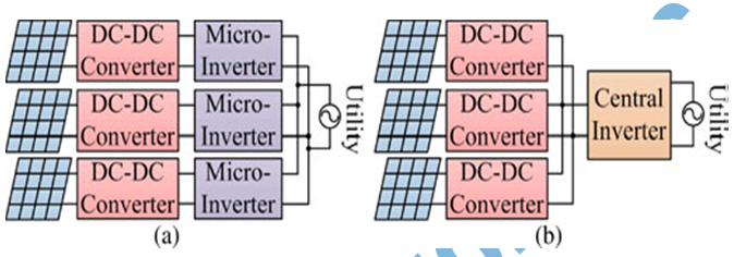
Fig. 1. Distributed (a)microinverter and (b) microconverter system structures.


Conclusion:
 As a solution for providing efficient, distributed PV conversion, an isolated boost resonant converter has been proposed. The system is a hybrid between a traditional CCM boost converter and a series-resonant half-bridge, employing only two active switches. The synthesis of the converter was described along with the circuit operating modes and key waveforms. The design process was then defined, with a focus on the unique combined resonant and PWM behavior. The result was a simple process, requiring only consideration of the resonant period length in selecting a valid converter duty cycle range. Also provided
was a detailed theoretical loss analysis, along with formulas for calculating the rms values of important waveforms. Finally, the loss and theoretical analysis were verified by the design, construction, and testing of a 250-W experimental prototype. The principle advantages of utilizing this topology were as follows:
1)      high weighted efficiency because of low circulating energy and reduced switching loss with  
      resonant energy transfer and output diode ZCS;
2)      low potential cost due to minimal number of active devices and a small overall component    
      count;
3)      galvanic isolation allows for the use of high efficiency inverter stages without additional    concern over ground leakage current;
4)      reduced control complexity provides lower auxiliary power loss and simpler controller IC configurations.
Further efficiency improvements are possible with the addition of wide band gap semiconductor devices and passive component optimization.

References:
 [1] A. S. Masoum, F. Padovan, and M. A. S. Masoum, “Impact of partial shading on voltage- and current-based maximum power point tracking of solar modules,” in Proc. IEEE PES General Meet., 2010, pp. 1–5.
[2] B. Brooks and C. Whitaker. (2005). Guideline for the use of the Performance Test Protocol for Evaluating Inverters Used in Grid-Connected Photovoltaic Systems [Online]. Available: http://www.gosolarcalifornia. org/equipment/documents/Sandia_Guideline_2005.pdf
[3] W. Bower, C. Whitaker, W. Erdman, M. Behnke, and M. Fitzgerald. (2004). Performance Test Protocol for Evaluating Inverters Used in Grid-Connected Photovoltaic Systems [Online]. Available:http://www.gosolarcalifornia.org/equipment/documents/2004-11-22_Test_Protocol.pdf
[4] O. Lopez, R. Teodorescu, F. Freijedo, and J. DovalGandoy, “Leakage current evaluation of a single-phase transformerless PVinverter connected to the grid,” in Proc. IEEE Appl. Power Electron. Conf., 2007, pp. 907– 912.
[5] W. Yu, J.-S. Lai, H. Qian, and C. Hutchens, “High-efficiency MOSFET inverter with H6-type configuration for photovoltaic nonisolated ac-module applications,” IEEE Trans. Power Electron., vol. 26, no. 4, pp. 1253–1260, Apr. 2011

Friday, 24 October 2014

Diode Clamped Three Level Inverter Using Sinusoidal PWM

Diode Clamped Three Level Inverter Using Sinusoidal PWM
Abstract:
An inverter is a circuit which converts dc power into ac power at desired output voltage and frequency. The ac output voltage can be fixed at a fixed or variable frequency. This conversion can be achieved by controlled turn ON & turn OFF or by forced commutated thyristors depending on applications. The output voltage waveform of a practical inverter is non sinusoidal but for high power applications low distorted sinusoidal waveforms are required. The filtering of harmonics is not feasible when the output voltage frequency varies over a wide range. There is need for alternatives. Three level Neutral Point Clamped inverter is a step towards it.

Keywords:
1.      Harmonics
2.       Inverter
3.       THD
4.       PWM


Software: MATLAB/SIMULINK
        Fig.1. Diode Clamped Three Level Inverter

Conclusion:
In normal inverters odd harmonics are present which causes distortion of the output waveform. By using the “THREE LEVEL DIODE CLAMPED INVERTER” we can eliminate some number of harmonics hence increasing the efficiency of the inverter.

References:

 [1] A.Mwinyiwiwa, Zbigneiw Wolanski, ‘Microprocessor Implemented SPWM for Multiconverters with Phase-Shifted Triangle Carriers’ IEEE Trans. On Ind. Appl., Vol. 34, no. 3, pp 1542-1549, 1998.
[2] J. Rodriguez, J.S. Lai, F. Z. Peng, ’ Multilevel Inverters: A Survey of Topologies, Controls and Applications’, IEEE Trans. On Ind. Electronics, VOL. 49, NO. 4, pp. 724-738, AUGUST 2002
[3] D. Soto, T. C. Green, ‘A Comparison of High Power Converter Topologies for the Implementation of FACTS Controller’, IEEE Trans. On Ind. Electronics, VOL. 49, NO. 5, pp. 1072-1080, OCTOBER 2002.
[4] Muhammad H. Rashid, Power Electronics: Circuits, Devices and Applications, Third edition, Prentice Hall of India, New Delhi, 2004.
[5] Dr. P. S. Bimbhra, Power Electronics, Khanna Publishers, Third Edition, Hindustan Offset Press, New Delhi-28, 2004.

Control Strategy for Power Flow Management in a PV System Supplying DC Loads

Control Strategy for Power Flow Management in a PV System Supplying DC Loads
Abstract:
The growing concern for energy saving has increased the usage of LED-based street lights, electronic chokes, compact fluorescent lamps, and inverter-fed drives. Hence, the load profile seen by the electrical grid is undergoing a notable change as these devices have to operate from a dc source. Photovoltaics (PV) being a major energy source, the aforementioned loads can be connected directly to the dc bus. A grid-connected PV system involves a power source (PV array), a power sink (load), and two power sources/sink (utility and battery), and hence, a power
flow management system is required to balance the power flow among these sources. One such system is developed for selecting the operating mode of the bidirectional converter by sensing the battery voltage. The viability of the scheme has been ascertained by performing experimental studies on a laboratory prototype. The control strategy is digitally implemented on an Altera Cyclone II Field Programmable Gate Array (FPGA) board, and the algorithm is verified for different modes of operation by varying the load. Experimental results are presented to bring out
the usefulness of the control strategy.

Keywords:
1.      Bidirectional converter
2.      DC bus
3.      Photovoltaic
4.      Power flow management system (PMS)


Software: MATLAB/SIMULINK

Fig.1.Grid-connected PV system with ac and dc loads

Conclusion:
A versatile control strategy for power flow management in a grid-connected PV system feeding dc loads has been presented. The importance of the scheme has been brought out by performing
experimental studies on a laboratory prototype. The steady-state performance of the converter for different modes of operation has been observed, and near unity power factor has been achieved in both the rectifier and inverter modes. The transient performance of the system for step changes in load and insolation have been also illustrated. The control strategy has been digitally implemented on an Altera Cyclone II FPGA board, and the algorithm has been verified for different modes of operation by varying the load, and a good correlation between the results of computer simulation and experiments has established the validity of the PMS. The significance of the proposed scheme has been demonstrated by its effectiveness in preventing undesirable shuttling of the PV operating point and also in maintaining the THD of the injected grid current within the allowable limit of 5% by setting a minimum current reference for injection. The proposed configuration has been proved to be attractive from the perspective of providing uninterruptible power to dc loads while ensuring the evacuation of excess PV power of high quality into the grid.
  
References:
[1] Yazdani and P. P. Dash, “A control methodology and characterization of dynamics for a photovoltaic system interfaced with a distribution network,” IEEE Trans. Power Del., vol. 24, no. 3, pp. 1538–1551, Jul. 2009.
[2] X. Q. Guo and W. Y. Wu, “Improved current regulation of three-phase grid-connected voltage-source inverters for distributed generation systems,” IET Renew. Power Gener., vol. 4, no. 2, pp. 101–115, Mar. 2010.
[3] H. C. Chiang, T. T. Ma, Y. H. Cheng, J. M. Chang, and W. N. Chang, “Design and implementation of a hybrid regenerative power system combining grid-tie and uninterruptible power supply functions,” IET Renew. Power Gener., vol. 4, no. 1, pp. 85–99, Jan. 2010.
[4] F. Giraud and Z. M. Salameh, “Steady-state performance of a grid connected rooftop hybrid wind–photovoltaic power system with battery storage,” IEEE Trans. Energy. Convers., vol. 16, no. 1, pp. 1–7, Mar. 2001.
[5] J. M. Carrasco, L. G. Franquelo, J. T. Bialasiewicz, E. Galvàn, R. C. P. Guisado, M. A. M. Prats, J. I. León, and N. Moreno-Alfonso, “Power electronic systems for the grid integration of renewable energy sources: A survey,” IEEE Trans. Ind. Electron., vol. 53, no. 4, pp. 1002– 1016, Aug. 2006.

Monday, 20 October 2014

Performance of the Speed Sensorless Induction Motor Drive for Traction Application with MRAS type Speed and Flux Estimator

Performance of the Speed Sensorless Induction
Motor Drive for Traction Application with MRAS
type Speed and Flux Estimator

ABSTRACT:

In the paper the Model Reference Adaptive System (MRAS) type estimator is applied in the sensorless Direct Torque Control with Space Vector Modulation (SVM-DTC) of Induction Motor (IM) drive. Sensorless control algorithm is tested on the traction 50kW induction motor drive. Whole control structure was implemented in the laboratory set-up with DS1103 card with Power PC 750GX DSP processor using C language. Dynamical performance of the drive and the estimator properties in field weakening and low speed regions for traction drive system are presented.

SOFTWARE: MATLAB/SIMULINK


CONCLUSION:

In this paper the performance of the sensorless SVM-DTC control structure of the induction motor drive for traction application were presented. Stator flux and rotor speed are reconstructed using the MRASCC estimator. It was proved that this estimation technique is robust to the motor parameter changes (including no-load and nominal load operation as well as field-weakening operation, which are connected with changes of motor winding parameters in a wide range) and can be implemented in the safety industrial application, like e.g. traction. Sensorless control algorithm is stable in the whole speed reference changes – including zero speed and field weakening operation. Drive works properly with and without load torque. This rotor speed and flux estimator can be implemented in different control algorithms with or without speed control loop.

REFERENCES:
[1] P. Vas, Sensorless vector and direct torque control, Oxford University Press, New York, 1998.
[2] J. Holtz, “Sensorless Control of Induction Machines - With or Without Signal Injection?”, IEEE Trans. Ind. Electronics, vol. 53, no. 1, pp. 7-30, 2006.
[3] J.W. Finch, and D. Giaouris, “Controlled AC electrical drives," IEEE Trans. Industrial Electronics, vol. 55, no. 2, pp. 481-491, 2008. 480
[4] S. N. Vukosavic, A. M. Stankovic, “Sensorless Induction Motor Drive with a Single DC-Link Current Sensor and Instantaneous Active and Reactive Power Feedback”, IEEE Trans. Ind. Electr., vol. 48, no. 1, pp. 195-204, 2001.

[5] C. Conilh, M. Pietrzak-David, “Sensorless Traction System with Low Voltage High Current Induction Machine for Indoor Vehicle”, Proc. Of the IEEE/PEDS’2005 Confer., pp.50-55, 2005.

Power-Management Strategies for a Grid-Connected PV-FC Hybrid Systems

Power-Management Strategies for a Grid-Connected PV-FC Hybrid System


ABSTRACT:

This paper presents a method to operate a grid connected hybrid system. The hybrid system composed of a Photovoltaic (PV) array and a Proton exchange membrane fuel cell (PEMFC) is considered. The PV array normally uses a maximum power point tracking (MPPT) technique to continuously deliver the highest power to the load when variations in irradiation and temperature occur, which make it become an uncontrollable source. In coordination with PEMFC, the hybrid system output power becomes controllable. Two operation modes, the unit-power control (UPC) mode and the feeder-flow control (FFC) mode, can be applied to the hybrid system. The coordination of two control modes, the coordination of the PV array and the PEMFC in the hybrid system, and the determination of reference parameters are presented. The proposed operating strategy with a flexible operation mode change always operates the PV array at maximum output power and the PEMFC in its high efficiency performance band, thus improving the performance of system operation, enhancing system stability, and decreasing the number of operating mode changes.

KEYWORDS:
1. Distributed generation
2. Fuel cell
3. Mybrid system
4. Microgrid
5. Photovoltaic
6. Power management.

SOFTWARE: MATLAB/SIMULINK

BLOCK DIAGRAM:

Fig. 1. Grid-connected PV-FC hybrid system


CONCLUSION:
This paper has presented an available method to operate a hybrid grid-connected system. The hybrid system, composed of a PV array and PEMFC, was considered. The operating strategy of the system is based on the UPC mode and FFC mode. The purposes of the proposed operating strategy presented in this paper are to determine the control mode, to minimize the number of mode changes, to operate PV at the maximum power point, and to operate the FC output in its high-efficiency performance band. The main operating strategy, shown in Fig. 7, is to specify the control mode; the algorithm shown in Fig. 4 is to determine in the UPC mode.With the operating algorithm, PV always operates at maximum output power, PEMFC operates within the high-efficiency range , and feeder power flow is always less than its maximum value . The change of
the operating mode depends on the current load demand, the PV output, and the constraints of PEMFC and feeder power. With the proposed operating algorithm, the system works flexibly, exploiting maximum solar energy; PEMFC works within a high-efficiency band and, hence, improves the performance of the system’s operation.
The system can maximize the generated power when load is heavy and minimizes the load shedding area. When load is light, the UPC mode is selected and, thus, the hybrid source works more stably. The changes in operating mode only occur when the load demand is at the boundary of mode change ; otherwise, the operating mode is either UPC mode or FFC mode. Besides, the variation of hybrid source reference power is eliminated by means of hysteresis. In addition, the number of mode changes is reduced. As a consequence, the system works more stably due to the minimization of mode changes and reference value variation. In brief, the proposed operating algorithm is a simplified and flexible method to operate a hybrid source in a grid-connected microgrid. It can improve the performance of the system’s operation; the system works more stably while maximizing the PV output power.
For further research, the operating algorithm, taking the operation of the battery into account to enhance operation performance of the system, will be considered. Moreover, the application of the operating algorithm to a microgrid with multiple feeders and DGs will also be studied in detail.

REFERENCES:

[1] T. Bocklisch, W. Schufft, and S. Bocklisch, “Predictive and optimizing energy management of photovoltaic fuel cell hybrid systems with shorttime energy storage,” in Proc. 4th Eur. Conf. PV-Hybrid and Mini- Grid, 2008, pp. 8–15.
[2] J. Larmine and A. Dicks, Fuel Cell Systems Explained. New York: Wiley, 2003.
[3] W. Xiao, W. Dunford, and A. Capel, “A novel modeling method for photovoltaic cells,” in Proc. IEEE 35th Annu. Power Electronics Specialists Conf., Jun. 2004, vol. 3, pp. 1950–1956.
[4] D. Sera, R. Teodorescu, and P. Rodriguez, “PV panel model based on datasheet values,” in Proc. IEEE Int. Symp. Industrial Electronics, Jun. 4–7, 2007, pp. 2392–2396.
[5] C. Wang, M. H. Nehrir, and S. R. Shaw, “Dynamic models and model validation for PEM fuel cells using electrical circuits,” IEEE Trans. Energy Convers., vol. 20, no. 2, pp. 442–451, Jun. 2005.


Wednesday, 8 October 2014

Single Phase Grid-Connected Photovoltaic Inverter for Residential Application with Maximum Power Point Tracking

Abstract
This article proposes a topology for single-phase two stage grid connected solar photovoltaic (PV) inverter for residential applications. Our proposed grid-connected power converter consists of a switch mode DC-DC boost converter and a H-bridge inverter. The switching strategy of proposed inverter consists with a combination of sinusoidal pulse width modulation (SPWM) and square wave along with grid synchronization condition. The performance of the proposed inverter is simulated under grid-connected scenario via PSIM. Furthermore, the intelligent PV module system is implemented using a simple maximum power point tracking (MPPT) method utilizing power balance is also employed in order to increase the systems efficiency.

Keywords—Photovoltaic, DC-DC Boost Converter, MPPT, SPWM, Square Wave, Power Electronics, Grid Tie Inverter(GTI).


Block Diagram

Software: MATLAB/SIMULINK

REFERENCES
[1] W. Xiao, F. F. Edwin, G. Spagnuolo, J. Jatsvevich, “Efficient approach for modelling and simulating photovoltaic power system” IEEE Journal of photovoltaics., vol. 3, no. 1, pp. 500-508, Jan. 2013.
[2] E. Roman, R. Alonso, P. Ibanez, S. Elorduizapatarietxe, D. Goitia, “ Intelligent PV module for grid connected PV system,” IEEE Trans. Ind. Elecron., vol. 53, no. 4, pp. 1066-1072, Aug. 2006.
[3] J. A. Santiago-Gonzalez, J. Cruz-Colon, R. otero-De-leon, V. lopez- Santiago, E.I. Ortiz-Rivera, “ Thre phase induction motor drive using flyback converter and PWM inverter fed from a single photovoltaic panel,” Proc. IEEE PES General Meeting, pp. 1-6, 2011.
[4] M. D. Goudar, B. P. Patil, and V. Kumar, “ Review of topology for maximum power point tracking based photovoltaic interface,” International Journal of Research in Engineering Science &
Technology, vol.2, Issue 1, pp. 35-36, Feb 2011.
[5] S. Kjaer, J. Pedersen, and F. Blaabjerg, "A review of single-phase grid connected inverters for photovoltaic modules," Industry Applications, IEEE Transactions, vol. 41, no. 5, pp. 1292 - 1306, Sept. - Oct. 2005.
[6] T. K. Kwang, S. Masri, “ Single phase grid tie inverter for photovoltaic application,” Proc. IEEE Sustainable Utilization and Development in Engineering and Technology Conf., pp. 23-28. Nov 2010.
[7] V. Meksarik, S. Masri, S. Taib, and C. M. Hadzer(2003). “Simulation of parallel-loaded resonant inverter for photovoltaic grid connected,” National Power and Energy Conference (PECon), Malaysia
[8] N. Mohan, T. M. Undeland, & W. Robbins, Power Electronics, 3rd ed., Denvers, MA: John Wiley & Sons, Inc., 2006, pp. 211-214.
[9] M. H. Rashid, Power Electronics, Circuits, Devices, and Applications, 3rd ed. New Delhi: Prentice-Hall of India Private Limited, 2007 pp.253-256.