asokatechnologies@gmail.com 09347143789/09949240245

Search This Blog

Tuesday, 27 June 2017

Adaptive Hysteresis Band Current Control for Transformer-less Single-Phase PV Inverters


ABSTRACT
Current control based on hysteresis algorithms are widely used in different applications, such as motion control, active filtering or active/reactive power delivery control in distributed generation systems. The hysteresis current control provides to the system a fast and robust dynamic response, and requires a simple implementation in standard digital signal platforms. On the other hand, the main drawback of classical hysteresis current control lies in the fact that the switching frequency is variable, as the hysteresis band is fixed. In this paper a variable band hysteresis control algorithm will be presented. As it will be shown, this variable band permits overcoming the aforementioned problem giving rise to an almost constant switching frequency. The performance of this algorithm, together with classical hysteresis controls and proportional resonant (PR) controllers, has been evaluated in three different single-phase PV inverter topologies, by means of simulations performed with PSIM. In addition, the behavior of the thermal losses when using each control structure in such converters has been studied as well.


SOFTWARE: MATLAB/SIMULINK


BLOCK DIAGRAM:

Fig. 1. Basic Current Control Scheme in a single phase inverter.

EXPECTED SIMULATION RESULTS:

Fig. 2. Behavior of the current and the voltage at the output of the converter
when using the H5 topology.


Fig. 3. Behavior of the current and the voltage at the output of the converter
when using the HERIC topology.


Fig. 4. Behavior of the current and the voltage at the output of the converter
when using the or HB-ZVR topology.

CONCLUSION
A hysteresis current control algorithm based on an adaptive hysteresis band for single phase PV converter topologies has been presented in this paper. As it has been shown analytically and by means of simulations this algorithm permits obtaining a fixed switching frequency in all the tested topologies. The main drawback of the conventional fixed hysteresis band current control is that generates excessive current ripple because modulation frequency varies within a band. This modulation frequency variation makes complicated the output filter design. Adaptive hysteresis band current control keeps the good performance of the fixed band hysteresis current control and additionally permits an easier output filter design due that the switching frequency is almost constant. On the other hand, switching losses can be reduced by using this adaptive hysteresis band current control. The analyzed topologies are the more widely used in transformerless single-phase PV systems (H5 and HERIC). Based in the previously comparative simulations results it can be concluded that in the case of H5 topology losses are concentrated in S5. In case of HERIC topology losses are located among S1, S2, S3 and S4. Finally in HB-ZVR single phase topology, losses are located in S5. These results mean that in each case, the losses distribution is not the same and a different thermal design should be done.

REFERENCES
[1]   L. Malesani, P. Mattavelli, P. Tomasin, “High Performance Hysteresis Modulation Technique for Active Filters”, IEEE Transactions on Power Electronics, Volume 12, September 1997.
[2]   J. Holtz and S. Stadtfeld, “A Predictive Controller for the Stator Current Vector of AC Machine-fed from a Switched Voltage Source”, in Proc. Int. Power Electronics Conference Rec. (Tokyo), 1983, pp. 1665-1675.
[3]   M. Ciobotaru, R. Teodorescu, and F. Blaabjerg, “Control of Single-Stage Single-Phase PV Inverter”, European Conference on Power Electonics and Applications, 2005.
[4]   Y. Hayashi, N. Sato, K. Takahashi, “A Novel Control of a Current- Source Active Filter for ac Power System Harmonic Compensation”, IEEE Transactions on Industrial Applications, Vol. 27, No. 2, March/April 1991.

[5]   T. Kato, K. Miyao, “Modified Hysteresis Control with Minor Loops for Single-Phase Full-Bridge Inverters”, Doshisha University, Kyoto Japan, 88CH2565-0/88/0000-0689$01.00, 1988 IEEE.

Friday, 16 June 2017

A Boost Dc - Ac Converter: Operation, Analysis, Control and Experimentation


 ABSTRACT

This paper proposes a new voltage source inverter referred to as boost inverter or boost DC - AC converter. The main attribute of the new inverter topology is the fact that it generates an AC output voltage larger than the DC input one, depending on the instantaneous duty - cycle. This property is not found in the classical voltage source inverter which produces an AC output instantaneous voltage always lower than the DC input voltage. Operation, analysis, modulation, control strategy and experimental results are included in this paper. The new inverter is intended to be used in UPS design, whenever an AC voltage larger than the DC link voltage is needed, with no need of a second power conversion stage.


SOFTWARE: MATLAB/SIMULINK

 CIRCUIT DIAGRAM:
Fig. 1 Circuit used to generate an AC voltage larger than the DC input voltage.

Fig. 2 (a) The current bi-directional boost converter and (b) The proposed
DC - AC boost converter.

EXPECTED SIMULATION RESULTS:

Fig 3. Output voltage.

Fig. 4 Current ofthe power supply

Fig.5 current of the inductor L1

Fig.6 voltage of the capacitor C1

Fig. 7 Output voltage

Fig. 8 Current of the power supply.

Fig. 9 Current of the inductor L1.

 Fig. 10 Voltage of the capacitor C 1.

Fig. 11 Output Voltage with 20 Hz sinusoidal reference signal.

Fig.12 output voltage with 20Hz triangular reference signal

Fig. 13 Output Voltage with 40 Hz sinusoidal reference signal.

 Fig. 14 Output Voltage with 40 Hz triangular reference signal.

CONCLUSION


This paper presents a new type of DC - AC converter, referred to as boost inverter. The active switches (IGBT's) are operated at a fixed frequency with the duty cycle around 50 YO, which allows the use of a simple gate drive. The circuit operation has been described and discussed. the effects are verified experimentally on a 270 W - 20 kHz breadboard. The new inverter is applicable in UPS design, whenever a AC voltage larger than the DC link voltage is needed, with no need of a second power conversion stage.

REFERENCES
[1]. V. VorpCrian, "Simplified Analysis of PWM Converters Using the Model of the PWM Switch Part I: Continuous Conduction", Proceeding of the VPEC seminar, Blacksburg, VA, pp 1-9, 1989.
[2] R. Tymerski, V. Vorperian, F.C. Lee and W. Baumann "Nonlinear Modelling of the PWM Switch" IEEE Power Electronics Specialists Conference 1988, pp 968 -976.


Thursday, 15 June 2017

A Review on PFC Cuk Converter Fed BLDC Motor Drive Using Artificial Neural Network


ABSTRACT
In this paper a Power Factor Correction Cuk converter fed Brushless DC Motor Drive using a Artificial Neural Network is used. The Speed of the Brushless dc motor is controlled by varying the output of the DC capacitor. A Diode Bridge Rectifier followed by a Cuk converter is fed into a Brushless DC Motor to attain the maximum Power Factor. Here we are evaluating the three modes of operation in discontinuous mode and choosing the best method to achieve maximum Power Factor and to minimize the Total Harmonic Distortion. We are comparing the conventional PWM scheme to the proposed Artificial neural network. Here simulation results reveal that the ANN controllers are very effective and efficient compared to the PI and Fuzzy controllers, because the steady state error in case of ANN control is less and the stabilization if the system is better in it. Also in the ANN methodology the time taken for computation is less since there is no mathematical model. The performance of the proposed system is simulated in a MATLAB/Simulink environment and a hardware prototype of the proposed drive is developed to validate its performance.

KEYWORDS:
1.      Brushless dc motor,
2.      Discontinuous input inductor mode
3.      Discontinuous output inductor mode
4.      Discontinuous intermediate capacitor mode
5.      Cuk converter
6.      Power Factor Correction
7.      Total Harmonic Distortion
8.      Artificial Neural Network
9.      Pulse width modulation

SOFTWARE: MATLAB/SIMULINK
  
BLOCK  DIAGRAM:


Fig 1.Proposed Scheme using Artificial Neural Network


EXPECTED SIMULATION RESULTS:

Fig 2.Simulation Waveforms a) Input voltage (Vin) b) Input current (Iin) c) Output voltage(Vcd)


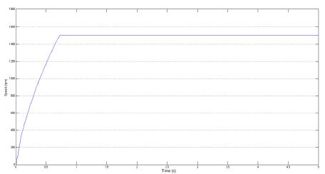
Fig.3 a)Speed(rpm) b)Electromagnetic torque(Nm) c)Power factor


Fig 4 Stator back emfs (Ea,Eb,Ec)

CONCLUSION
A Power Factor Corrected Cuk converter fed BLDC motor using Artificial neural network is simulated in the environment of MATLAB. A Diode Bridge Rectifier followed by a Cuk converter is fed into a Brushless DC Motor to attain the maximum Power Factor. Here we are evaluating the three modes of operation in discontinuous mode and choosing the best method to achieve maximum Power Factor and to minimize the Total Harmonic Distortion.The three modes Discontinuos DICM(Li),DICM(Lo),DCVM(Vco) is simulated at the given switching frequency 20Khz.The diode bridge followed by a Cuk converter is used here for maximum Power Factor Correction.The power factor obtaine in ANN is 0.9818 which is near to unity. The main advantage of using Artificial neural network is that in conventional PI only one value that is feed back is selected and comparing and producing the gating pulse but in our proposed scheme a set of values is compared and we are choosing the best out of them.


REFERENCES
[1]   J. F. Gieras and M.Wing, Permanent Magnet Motor Technology—Design and Application. New York, NY, USA: Marcel Dekker, Inc, 2002.
[2]   C. L. Xia, Permanent Magnet Brushless DC Motor Drives and Controls.Beijing, China: Wiley, 2012.
[3]   Y. Chen, C. Chiu, Y. Jhang, Z. Tang, and R. Liang, “A driver for the singlephase brushlessDCfan motor with hybrid winding structure,” IEEE Trans.Ind. Electron., vol. 60, no. 10, pp. 4369–4375, Oct. 2013.
[4]   S. Nikam, V. Rallabandi, and B. Fernandes, “A high torque density permanent magnet free motor for in-wheel electric vehicle application,” IEEE Trans. Ind. Appl., vol. 48, no. 6, pp. 2287–2295, Nov./Dec. 2012.

[5]   X. Huang, A. Goodman, C. Gerada, Y. Fang, and Q. Lu, “A single sided matrix converter drive for a brushless DC motor in aerospace applications,” IEEE Trans. Ind. Electron., vol. 59, no. 9, pp. 3542–3552, Sep. 2012..

Analysis of PFC Cuk and PFC Sepic Converter Based Intelligent Controller Fed BLDC Motor Drive


ABSTRACT
This paper deals with a highly reliable electrical drive utilizing the Brushless DC Motor (BLDC). The motor is fed by Voltage source Inverter (VSI) with a dc-dc converter power factor correction circuit (PFC) as the VSI’s predecessor. The Performance of two dc-dc converters (cuk and sepic as PFC) are analyzed and the results are discussed to arrive at the best suited converter. Fuzzy Logic Controller is used as the Intelligent Controller for the BLDC motor. Reliable, low cost arrangement is thus provided to achieve unity power factor and speed regulation with accuracy. The drive has been simulated using the MATLAB/Simulink environment and the performance has been studied.

KEYWORDS:
1.      Brushless DC Motor (BLDC)
2.      Power Quality (PQ)
3.      Power factor correction (PFC)
4.      Cuk converter
5.      Sepic converter
6.      Fuzzy logic controller (FLC).

SOFTWARE: MATLAB/SIMULINK


BLOCK  DIAGRAM:

Fig. 1. Block diagram

SIMULINK MODEL DIAGRAMS:


Fig. 2. PFC cuk fed BLDC

Fig. 3. PFC Sepic fed BLDC


EXPECTED SIMULATION RESULTS:


Fig. 4. Input power factor

Fig. 5. Cuk Converter Efficiency

Fig. 6. Motor Speed

Fig. 7. Input power factor

Fig. 8. Sepic Converter Efficiency

Fig. 9. Motor Speed


CONCLUSION
The power factor correction has been successfully implemented using the cuk and sepic converter. It shows a much improved result as it not only provides better power quality, but also the converter removes the necessity to smooth out the dc output from ripples. The fuzzy logic controller widely increases application range of the motor by increasing the reliability. The motor is presently used in areas such as aerospace, aircraft and mining applications because of the enhanced reliability that the motor offers. This is further enhanced by the usage of FLC and the PFC converters. The FLC is used to control the motor speed and the cuk or sepic converter is used for the power factor improvement. It is found that the sepic converter is found to provide better power quality. The Analysis has been done for Continuous conduction in the sepic and cuk converters as both are not capable of self PFC.

REFERENCES
[1]   R.Shanmugasundram, K. Muhammad Zakariah and N. Yadaiah, “Implementation and Performance Analysis of Digital Controllers for Brushless DC Motor Drives,” IEEE/ASME Trans. Mechatronics, vol. 19, no. 1, Feb. 2014.
[2]   T. Kenjo and S. Nagamori, Permanent Magnet Brushless DC Motors.Oxford, U.K.: Clarendon Press, 1985.
[3]   Sanjeev Singh and Bhim Singh, “A Voltage-Controlled PFC Cuk Converter-Based PMBLDCM Drive for Air-Conditioners,” IEEE Trans. Ind. Appl. vol. 48, no. 2, Mar. /Apr. 2012.
[4]   Vashist Bist and Bhim Singh, “PFC CUK Converter-Fed BLDC Motor Drive,” IEEE Trans. Power Electron., vol. 30, no 2, Feb. 2015.

[5]   “Limits for harmonic current emissions (equipment input current16 A per phase),” International Standard IEC 61000-3-2, 2000

Wednesday, 14 June 2017

Analysis of Performance of the Induction Motor under Hysteresis Current Controlled DTC


ABSTRACT:
The direct torque control method is a powerful control technique for specially induction motor drive due its fast dynamic torque response. It originates in the fact that torque and flux is directly controlled by instantaneous space voltage vector unlike. Field Oriented Control (FOC) and smooth control of drives are being utilized to perform real time simulation on the ac motor variables, such as electromagnetic torque, fluxes, mechanical speed, etc. For the reason, direct torque control gradually has been used in the field requiring fast response since its introduction in the mid-1980. Even though the direct torque control has several problems. These problems are: (I) low switching frequency and variation in speed; (2) the increase of the torque ripple in the low speed region; (3) the short control period (25 /ls) for the good performance. To solve the problems of Direct Torque Control, several studies were carried out. This paper improves one of the drawbacks of Direct Torque Control with the Hysteresis direct torque control. In some papers to avoid these problems 2 level inverter with induction motor has been used but it is very complicated and didn't show large improvement. In this paper, Hysteresis direct torque control method with 3 level inverter has been implemented and its effectiveness is compared with conventional direct torque control with 2 level inverter by using Matlab/Simulink.

KEYWORDS:
1.Direct Torque Control
2. Hysteresis Direct Torque Control
3. 2 Level Inverter
4. 3 Level Inverter.

SOFTWARE: MATLAB/SIMULINK

BLOCK DIAGRAM:


.

EXPECTED SIMULATION RESULTS:


Fig.9. Simulated XY plot wave form of flux current with Hysteresis current controlled DTC


CONCLUSION:
In the present work initially the modeling and simulation of a three phase three level synchronous link converter using hysteresis controller and adaptive hysteresis controller is presented. The hysteresis controller for the 3 level converters is designed and developed in the Simulink model. The modeling, simulation of a direct torque and direct flux control of an induction motor fed from a three phase three level inverter is presented in this paper. The effectiveness of the proposed 3 level inverter fed induction motor drive controlled with hysteresis current controlled DTC is compared with 2 level inverter fed induction motor drive with conventional DTC and it is observed in simulation results the improvement in low speed operation performance of induction motor for high power three level inverter applications


REFERENCES:
[I] Rakesh Kantaria and S.K.Joshi "A review on power quality problems and solutions" Power electronics National Conference November 2008.
[2]IEEE Std. 1159 - 1995, "Recommended Practice for Monitoringn Electric Power Quality.
[3]Yan Li, Chengxiong Mao, Buhan Zhang, Jie Zeng, "Voltage Sag Study for a Practical Industrial Distribution Network", 2006 International Conference on Power System Technology, pp.I-4, Oct., 2006.
[4]Understanding FACTS: Concepts and Technology of Flexible AC Transmission Systems. Narain G. Hingorani, Laszlo Gyugyi. Wiley IEEE press.
[5] J. G. Nielsen, M. Newman, H. Nielsen, and F. Blaabjerg, "Control and testing of a dynamic voltage restorer (DVR) at medium voltage level,"iEEE Trans. Power Electron., vol. 19, no. 3,p.806,May 2004

Novel Direct Torque Control Based On Space Vector Modulation With Adaptive Stator Flux Observer For Induction Motors


ABSTRACT:


This paper describes a combination of direct torque control (DTC) and space vector modulation (SVM) for an adjustable speed sensorless induction motor (IM) drive. The motor drive is supplied by a two-level SVPWM inverter. The inverter reference voltage is obtained based on input-output feedback linearization control, using the IM model in the stator – axes reference frame with stator current and flux vectors components as state variables. Moreover, a robust fullorder adaptive stator flux observer is designed for a speed sensorless DTC-SVM system and a new speed-adaptive law is given. By designing the observer gain matrix based on state feedback control theory, the stability and robustness of the observer systems is ensured. Finally, the effectiveness and validity of the proposed control approach is verified by simulation results.

KEYWORDS:

1. Adaptive stator flux observer
2. Direct torque control
3. Feedback linearization
4. Robust
5. Space vector modulation

SOFTWARE: MATLAB/SIMULINK


BLOCK DIAGRAM:


Fig. 1.The block diagram of the DTC-SVM system

SIMULATION RESULTS:

 Fig. 2. Speed and torque response curve of conventional DTC.  Fig. 3. Speed and torque response curve of proposed                                                                                                                                         DTC-SVM.


CONCLUSION:
A novel DTC-SVM scheme has been developed for the IM drive system, which is on the basis of input-output linearization control. In this control method, a SVPWM inverter is used to feed the motor, the stator voltage vector is obtained to fully compensate the stator flux and torque errors. Furthermore, a robust full-order adaptive flux observer is designed for a speed sensorless DTCSVM system. The stator flux and speed are estimated synchronously. By designing the constant observer gain matrix based on state feedback H∞ control theory, the robustness and stability of the observer systems is ensured. Therefore, the proposed sensorless drive system is capable of steadily working in very low speed, has much smaller torque ripple and exhibits good dynamic and steady-state performance.

REFERENCES:
[1] I. Takahashi and T. Noguchi, “A new quick-response and high efficiency control strategy of an induction motor,” IEEE Trans. Ind. Appl., vol. IA-22, no. 5, pp. 820–827, 1986.
[2] Y. S. Lai and J. H. Chen, “A new approach to direct torque control of induction motor drives for constant inverter switching frequency and torque ripple reduction,” IEEE Trans. Energy Convers., vol. 16, no. 3, pp. 220–227, 2001.
[3] S. Mir, M. E. Elbuluk, and D. S. Zinger, “PI and fuzzy estimators for tuning the stator resistance in direct torque control of induction machines,” IEEE Trans. Power Electron., vol. 13, no. 2, pp. 279–287, 1998.
[4] F. Bacha, R. Dhifaoui, and H. Buyse, “Real-time implementation of direct torque control of an induction machine by fuzzy logic controller,” in Proc. ICEMS, 2001, vol. 2, pp. 1244–1249.
[5] A. Arias, J. L. Romeral, and E. Aldabas, “Fuzzy logic direct torque control,” in Proc. IEEE ISIE, 2000, vol. 1, pp. 253–258.