ABSTRACT
This paper proposes a new voltage source inverter referred
to as boost inverter or boost DC - AC converter. The main attribute of the new
inverter topology is the fact that it generates an AC output voltage larger
than the DC input one, depending on the instantaneous duty - cycle. This property is not found in the
classical voltage source inverter which produces an AC output instantaneous
voltage always lower than the DC input voltage. Operation, analysis,
modulation, control strategy and experimental results are included in this paper.
The new inverter is intended to be used in UPS design, whenever an AC
voltage larger than the DC link voltage is needed, with no need of a second
power conversion stage.
SOFTWARE: MATLAB/SIMULINK
CIRCUIT
DIAGRAM:

Fig. 1 Circuit used to generate an
AC voltage larger than the DC input voltage.

Fig. 2 (a) The current bi-directional boost
converter and (b) The proposed
DC -
AC boost converter.
EXPECTED
SIMULATION RESULTS:


This paper presents a new type of DC - AC converter, referred to as boost inverter. The active switches (IGBT's) are operated at a fixed frequency with the duty cycle around 50 YO, which allows the use of a simple gate drive. The circuit operation has been described and discussed. the effects are verified experimentally on a 270 W - 20 kHz breadboard. The new inverter is applicable in UPS design, whenever a AC voltage larger than the DC link voltage is needed, with no need of a second power conversion stage.
Fig 3. Output voltage.
Fig. 4 Current ofthe power supply
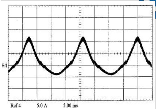
Fig.5 current of the inductor L1
Fig.6 voltage of the capacitor C1
Fig. 7 Output voltage
Fig. 8 Current of the power supply.
Fig. 9 Current of the inductor L1.
Fig. 10 Voltage of the capacitor C 1.
Fig. 11 Output Voltage with 20 Hz sinusoidal reference signal.
Fig.12 output voltage with 20Hz triangular reference signal
Fig. 13 Output Voltage with 40 Hz sinusoidal reference signal.
Fig. 14 Output Voltage with 40 Hz triangular reference signal.
| CONCLUSION |
This paper presents a new type of DC - AC converter, referred to as boost inverter. The active switches (IGBT's) are operated at a fixed frequency with the duty cycle around 50 YO, which allows the use of a simple gate drive. The circuit operation has been described and discussed. the effects are verified experimentally on a 270 W - 20 kHz breadboard. The new inverter is applicable in UPS design, whenever a AC voltage larger than the DC link voltage is needed, with no need of a second power conversion stage.
REFERENCES
[1]. V. VorpCrian, "Simplified Analysis of PWM Converters Using the Model of the PWM Switch Part I: Continuous Conduction", Proceeding of the VPEC seminar, Blacksburg, VA, pp 1-9, 1989.
[2] R. Tymerski, V. Vorperian, F.C. Lee and W. Baumann "Nonlinear Modelling of the PWM Switch" IEEE Power Electronics Specialists Conference 1988, pp 968 -976.